
Piping 3D
With Piping 3D you design building-services and process piping in 3D: drinking water, heating, cooling, gas and process lines. You first draw the route line – the axis of the pipe – and let LuaCAD create pipes, elbows, tees and reducers from the chosen catalog ("Generate 3D"). Or you generate the 3D right while drawing.
Overview
A pipe run is created step by step:
- On the Pipe page of the panel choose the medium, catalog, nominal size (DN) and height.
- Click Insert and click the run point by point into the drawing – see Inserting a pipe.
- Generate 3D: pipes and fittings are created from the catalog. If you change the route line afterwards (grips, move, stretch), the 3D follows.
- Insert valves, products and custom components into the pipe – see Inserting parts.
- Output isometrics, parts and material lists, annotation and IFC.
| Page | What you will find |
|---|---|
| Pipes | Inserting a pipe, multi-pipe runs, connecting two pipes |
| Inserting parts | Fittings by hand, inserting parts into a pipe, mounted instruments, custom symbols |
| Connections | Placing pipe connections, defining the connections of custom components |
| Editing | Selecting several, moving pipes, stretching (accordion) |
The pages of the panel
Each page of the panel has an "i" at the top with a short explanation; "More in the online help" leads to the sections here.
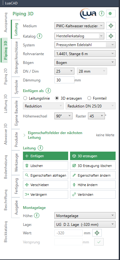
- The pages of the panel: Pipe, Risers/connections, Symbols, Custom components, Products, Tools, Fabrication, Output.
- Medium, catalog, nominal size, insulation – what the next pipe is made of.
- Insert as – route line, 3D right away, or a single fitting; plus the height change and the angle grid.
- Insert starts the pipe; the buttons next to it change what is already there.
- Installation level – the height of the next pipe.
Pipe
At the top you choose what the next pipe is made of: medium, catalog, nominal size and insulation. "Insert as" decides whether only the route line is created (the pipes follow later with "Generate 3D"), whether pipes and fittings are inserted while you draw, or whether you insert a single fitting. The installation level sets the height: absolute, from the storey (top of slab, underside of slab, finished floor, underside of ceiling + value), an installation level, or "free" (the height of the point you click).
Risers/connections
A riser template describes several pipes side by side, for example cold water, hot water and circulation; a connection template describes the connections of a fixture. "Insert riser/connections" places risers or pipe connections; "Insert multi-pipe run" draws all pipes of the riser template in parallel – see Multi-pipe run.
Symbols
Insert valve symbols into a pipe: click a symbol, then the pipe – the symbol sits there and the pipe runs through it. Symbols with only one connection attach to the end of a pipe. You create your own symbols with the symbol wizard.
Custom components
A custom component is a DWG with defined connections (pump, storage tank, manifold …). Choose a folder and a component, click Insert and click a point on the pipe – see Inserting a part into a pipe. A grey entry has no connections yet: define connections.
Products
Products from manufacturer catalogs, and neutral valves without a manufacturer for early design. Choose a product, click Insert and click a point on the pipe. Pressure gauges, thermometers and air vents sit on the pipe – see Mounted instrument.
Tools
Change existing pipes: move, connect, split, height and properties. "Generate 3D" and "Delete 3D", switch the display, convert 2D to 3D and check for clashes.
Fabrication
What the workshop needs: branch outlets, welds, flanges and bolts, the isometric with flow direction, spools and the PCF export.
Output
Position numbers, parts and material lists (as a table in the drawing or as a file, also across several plans), annotation from templates and level symbols.
Keys at the cursor
While a function runs, the action bar at the cursor shows every key that currently applies – to click or to press. The same key means the same thing in every module:
| Key | Meaning |
|---|---|
| A | type a distance, height or length |
| R | rotate with the mouse |
| D | type an angle |
| W | pick an angle (two clicks) |
| F | hold at a connection |
| Z | pull away from the connection – a pipe is created in between |
| P | take values from the drawing |
| N | take only the medium |
| S | switch the side of a multi-pipe run |
| Space | another grip point, or snap angle / free |
| Enter | finish |
| Esc | cancel |
The Help chip in the bar opens the help for the running function.