
Drainage 3D
With Drainage 3D you design the drainage of a building in 3D: fixture drains, horizontal branches and building drains, stacks, in-wall carriers, manholes and trench drains. You work almost entirely in plan view: you place the connectors (stack, fixtures) and sketch the pipe between them as a plumbing line. Only Generate 3D turns this into pipes and fittings – sized to the chosen standard and with the slope built up from the stack.
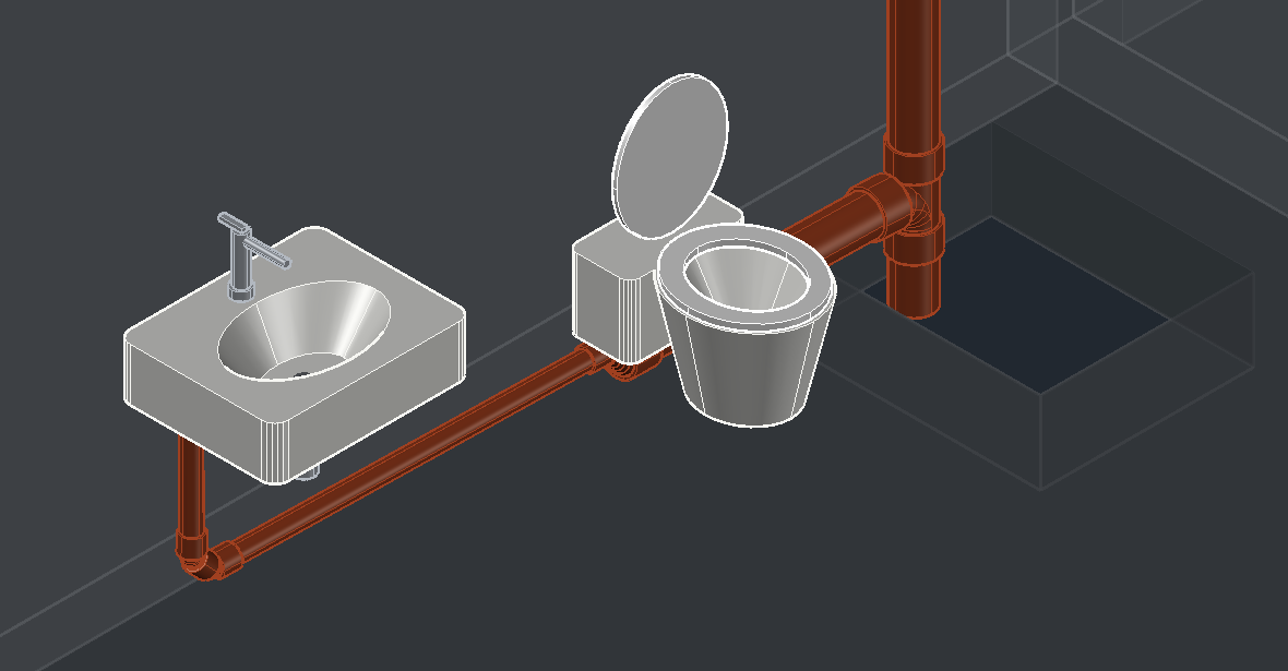
How this help is organized
From overview to detail – read only as far as you need right now:
| Part | What you will find | For whom |
|---|---|---|
| Quick start | Sketch a small drainage network in a few steps, generate 3D and make simple changes – one picture per step. | Anyone drawing their first network today |
| Basic concepts | Plumbing line, Generate 3D and fitting by hand; drainage network, stack, fixture, standard, slope, DU, reducer, branch offset, elevations, in-wall carrier. | Anyone who wants to understand how Drainage 3D works |
| Tasks | Every function of the palette and of the action bar in detail: goal, steps, keys, options, example, notes – with a short video at the end. | Anyone who needs a particular function |
| Reference | All buttons per palette page, all keys, the gear menu, the dialog boxes and every setting with its default value. | Anyone looking for something specific |
The tasks are ordered by work step: General routing, In-wall carrier routing, Connectors, Fittings and custom parts, Accessories, Editing and tools and Output.
What works the same in all plug-ins – palette, gear menu, entering values, choosing the elevation, selecting objects, systems, levels, drawing units – is described under Getting started.
Overview
A drainage network is created step by step:
- At the top of the palette choose the level and the system (for example wastewater) – they apply to everything you insert from now on.
- General routing page, step 1: insert the stack down – this is where the water leaves – and then the fixtures (lavatory, toilet, shower …).
- Step 2: with Insert line sketch the pipe in plan, from connector to connector. Crossing is allowed – a branch is created there later.
- Step 3: Generate 3D. Pipes and fittings are created to the standard, with slope from the stack. What does not work is shown in a list and as a red marker in the drawing.
- Add vertical and special parts by hand (Fittings), place accessories (Accessories), annotate and output lists (Output).
If you later change a line or a connector, simply generate the 3D again – fittings placed by hand stay.
| Page | What you will find |
|---|---|
| General routing | Inserting connectors, inserting and editing plumbing lines, snap to angle, generating and deleting 3D, the result |
| In-wall carrier routing | Stack, fixtures and carrier line of an in-wall carrier, generating its 3D |
| Connectors | All connector types, templates, offset, spot elevation, stack across several levels, connector dialog box |
| Fittings and custom parts | Single fitting, combination, connecting and inserting in-line, shortening, connecting two ends, custom parts |
| Accessories | Electrofusion coupling, pipe clamps, wall flange, insulation, manhole, trench drain |
| Editing and tools | Selecting, properties, Move, Delete, Renumber, Reassign, error markers, Check 3D, clashes |
| Output | Annotation, spot elevation and elevation, detail, parts list and bill of materials, lists across several drawings, cut list |
The pages of the palette
Open the palette from the ribbon › LuaCAD tab › Drainage 3D. Level and system are at the top above all pages; at the bottom of every page you find Generate 3D, Delete 3D, Properties, Move and Delete – reachable from any page. Each page has an "i" at the top with a short explanation; "More in the online help" leads to the sections here. Every button is listed in the Reference.
General routing
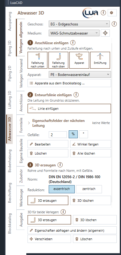
The horizontal drains in three steps: 1 Insert connectors (stack down, stack up, fixture, vent), 2 Insert plumbing line (with the slope of new lines), 3 Generate 3D (to the standard, with the choice of reducer). Every drainage network needs exactly one stack down and at least one inlet. "Properties" at the bottom takes only objects of "General routing" on this page.
Tasks on this page: Inserting connectors · Inserting a plumbing line · Editing a plumbing line · Snap to angle · Deleting lines · Generate 3D · Result · Delete 3D
In-wall carrier routing
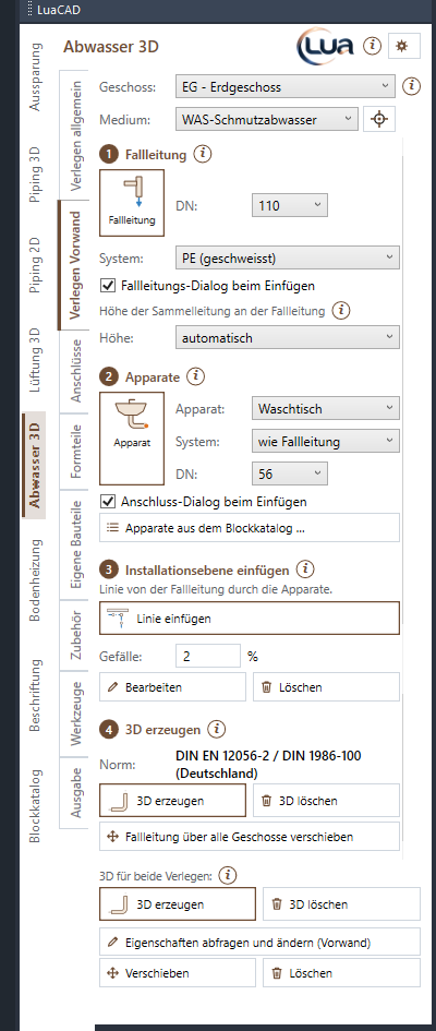
An in-wall carrier is built entirely in plan: stack, fixtures, a line through their connectors (the carrier line) and Generate 3D – LuaCAD calculates the elevations from the centerline elevations of the fixtures. Networks of the in-wall carrier and of "General routing" stay separate; you can always continue with fittings. "Properties" at the bottom takes only objects of the in-wall carrier on this page.
Tasks on this page: Stack of the in-wall carrier · Inserting a fixture · Carrier line · Editing and deleting · Generate 3D · Moving a stack across all levels
Connectors
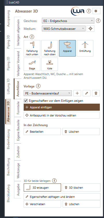
All connector types are on one page here – including the offset (a step in elevation) and the spot elevation (a fixed elevation on a line). A template stores the values of a connector and applies to every newly inserted one; you change connectors already inserted with Edit.
Tasks on this page: Types · Stack · Fixture or vent · Offset · Spot elevation · Templates · Base point · Stack across levels · Editing and deleting
Fittings
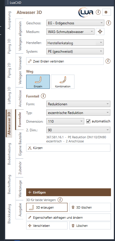
Here you build what "Generate 3D" does not – mostly the vertical parts: stacks, double 45° bends, branch offsets. Clicking a part shows it in the preview window, Insert in the footer puts it on the cursor. It connects to a free end or is inserted in-line into a pipe, and it stays when you generate the 3D again.
Tasks on this page: Manufacturer and product line · Single fitting · Combination · Inserting and connecting · Shortening · Connecting two ends
Custom parts
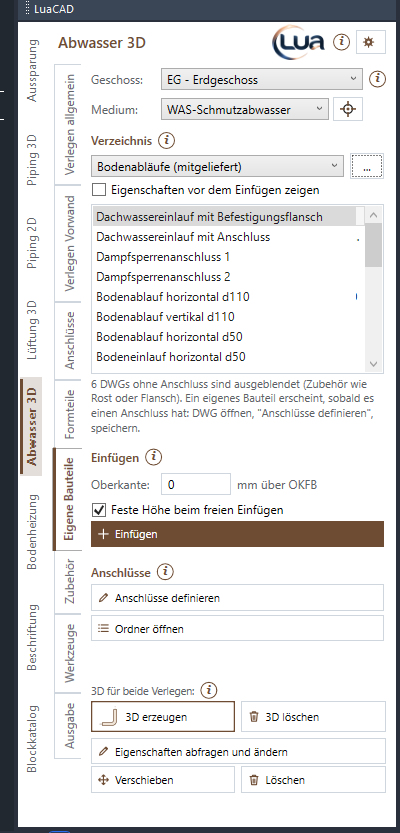
Every DWG in the folder is a part, for example a floor drain or a roof drain. The list shows only files with at least one connector. At the cursor the part connects to a free connector of the same DN, is inserted in-line into a pipe with two aligned connectors, or is inserted freely.
Tasks on this page: Inserting a custom part · Defining connectors
Accessories
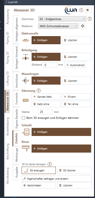
Electrofusion couplings, pipe clamps, wall flanges and insulation sit on the pipes. If you generate the 3D again, they move onto the new pipes. You insert manholes and trench drains freely; you choose their dimensions first in a dialog box.
Tasks on this page: Electrofusion coupling · Pipe clamps · Wall flange · Insulation · Manhole · Trench drain
Tools
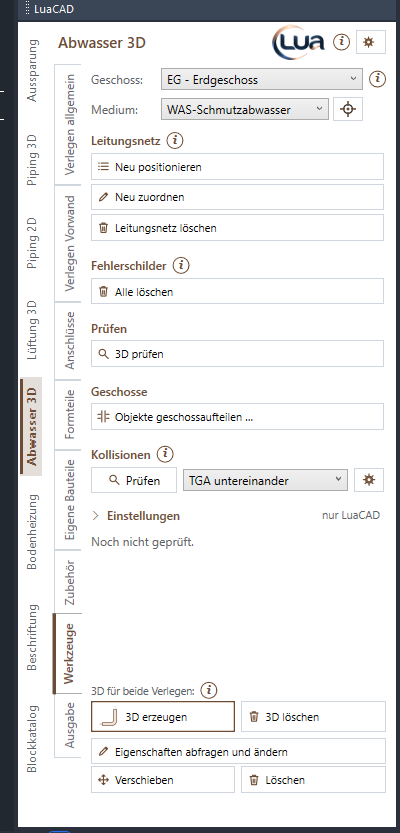
Change, check and clean up whole drainage networks: renumber parts, change the level, system or product line of many objects at once, delete a network, remove error markers, check the 3D for gaps, divide across levels and find clashes.
Tasks on this page: Renumber · Reassign · Delete drainage network · Error markers · Check 3D · Divide objects across levels · Clashes
Output
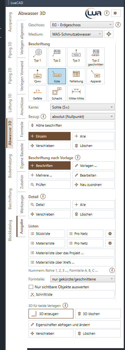
Annotations are attached to their part and stay up to date when it changes – even after "Delete 3D" and generating again. The parts list lists every item separately, the bill of materials adds up identical parts. In addition: details of the nodes and the cut list.
Tasks on this page: Annotation · Spot elevation and elevation · Annotation from template · Detail · Parts list and bill of materials · Across several drawings · Cut list
Keys at the cursor
While a function runs, the action bar at the cursor shows all keys that apply right now – to click or to press. The same key means the same in all plug-ins; the complete list is in the Reference.
| Key | Meaning |
|---|---|
| A | distance to a reference point; while drawing a plumbing line slope, elevation and wall offset |
| Space | while drawing "snap to angle" / "free"; when inserting a connector the line snap off/on or the next base point |
| L | line snap off/on while the Space key switches the base point |
| E | values of the next connectors |
| R | rotate (fitting), turn the arrow of an in-wall carrier fixture by 90° |
| H | centerline elevation of an in-wall carrier fixture; elevation only when moving |
| D / W | type an angle / pick it with two clicks |
| F / Z | hold a fitting at the connector / pull it away – a pipe is created in between |
| P / N | match properties / only the system of a clicked plumbing line |
| Enter | done |
| Esc | cancel – while drawing, the segments already placed stay |
The Help button in the action bar opens the help for the running function.