
Concepts
If you know these terms, you understand every function of Piping 2D. The tasks refer here when a term matters. General terms of all plug-ins (palette, system, layer, level, drawing units) are explained in Getting started › Concepts.
The 2D pipe
A pipe in Piping 2D is an ordinary line of the CAD (or a polyline if it is flexible) – no block, no solid. It lies in the drawing plane (elevation 0) and carries its pipe data: system, system elevation, size, flexible and radius. The geometry is the line itself; whatever you change on it with the CAD is the pipe right away.
- A pipe runs from one end to the next node (corner, branch, connector). At a tee Piping 2D breaks a pipe that runs through into two.
- At a crossing the lower pipe is interrupted in pieces – for lists, annotation and conversion it stays one pipe. If you select one piece, the others come along.
- A break point set by hand divides a straight pipe into two that never grow back together by themselves.
Rigid and flexible pipe
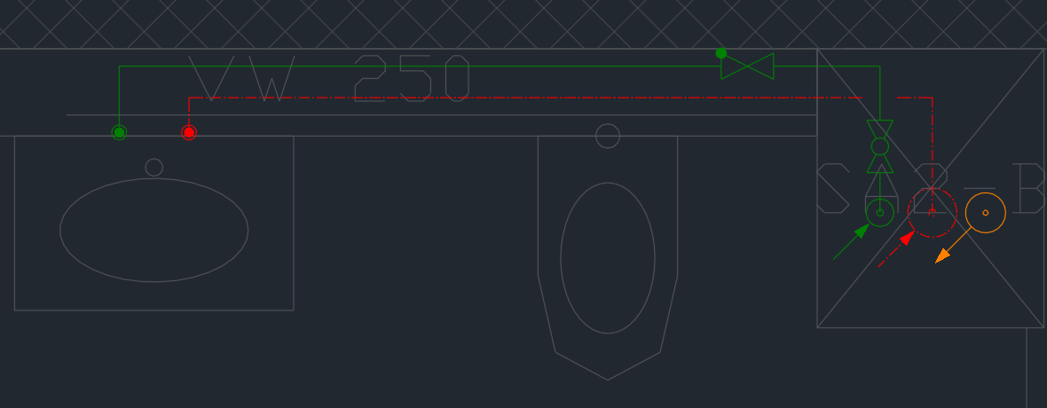
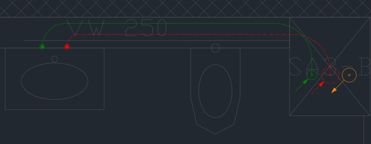
| rigid (default) | flexible | |
|---|---|---|
| Used for | copper, steel, plastic pipe in straight lengths | bendable pipes such as PEX or multilayer pipe from the coil |
| In the CAD | one line per segment | one polyline, an arc with the radius at every corner |
| Corners | sharp | rounded with the radius (default 300 mm); if it does not fit, a smaller radius is used – shown red at the cursor |
| Parallel pipes | corners mitered | arcs concentric |
| Bill of materials | "Pipe", length of the lines | "Pipe flexible", length along the arcs |
| Turn on | – | flexible check box on the Pipe page (new pipes) or Properties (existing pipes) |
Even when flexible, the pipe data reach to the corner point – only the display is rounded. Tools always write the pipe straight; the rounding is created again afterwards.
System elevation
The system elevation says in which zone of the building a pipe runs – for example in the floor, below the ceiling, in the wall. In Piping 2D it is a property, not an elevation value: everything is drawn at elevation 0. They are the same system elevations as in Piping 3D (gear menu › System elevations), with an abbreviation and a name.
- Every system elevation has its own linetype (gear menu › Elevation marking; default: first system elevation like the system, second dashed, third dash-dot).
- The system elevation decides which pipe lies on top at a crossing: the one with the higher elevation (in a level where all system elevations have a value), otherwise the one listed higher up.
- A pipe without a system elevation ("(no system elevation)") is allowed; it is the lower one at every crossing.
- When converting to 3D, the system elevation becomes the elevation of the pipe.
Crossing and elevation change
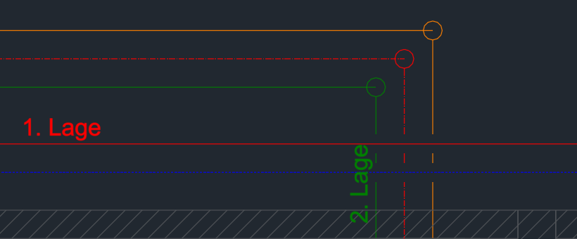
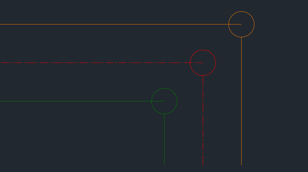
| Crossing | Elevation change | |
|---|---|---|
| When | Two pipes cross without being joined. | A pipe continues on another system elevation at a corner or branch. |
| What you see | The pipe on the lower system elevation has a real gap (default 50 mm), the upper one runs through. Same system elevation: no gap. | A circle around the corner (default 60 mm diameter). The upper pipe runs to the center, the lower one ends at the edge. At a tee the pipe that runs through stays whole. |
| How it is created | By itself with every change (draw, move, copy, delete); can be turned off in the gear menu › Elevation marking. | While drawing choose another system elevation with A, or connect to a pipe on another system elevation; likewise Change system elevation and Connect. |
| What it follows | The gap is set again with every change. | The circle follows the moved pipe. If both pipes have the same system elevation afterwards, it disappears. |
System
The system says what flows in the pipe – for example cold water, hot water, heating supply. It sets the color and the layer (for example LuaCAD_SAN_PWC-Kaltwasser reduziert). In the system definitions Piping 2D has its own list with its own display (the entries "single-line (2D pipe)" and "riser insulation circle") – independent of how Piping 3D shows the same system. Create and change them in the gear menu › Systems.
- A new pipe connects only to a pipe of the same system. A pipe of another system under the cursor does not snap.
- Two pipes of different systems clicked one by one (supply with return) can still be joined by Connect – the connecting piece carries the system of the pipe clicked first.
- The Pick button next to "System" takes the system of an existing pipe.
Size
Instead of a nominal size (DN) a 2D pipe carries a size in mm – optional. Empty means: no value. The size is used by the bill of materials (length per size), the annotation (field {Dimension}), the size of the riser circles (radius = half the size, without a size 50 mm) and the conversion to 3D. Where different sizes meet at a node, the bill of materials counts a reducer there.
Riser
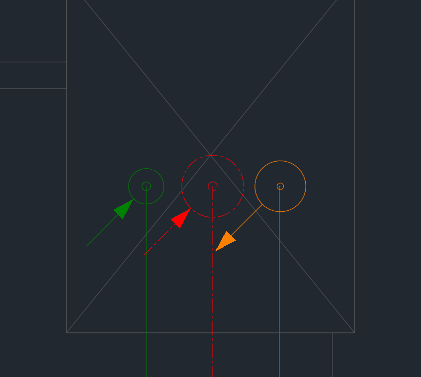
A riser is the sign of a vertical pipe in plan view: the rise/drop symbol, a circle with a line and an arrow. In Piping 2D a riser is only its symbol – there is no vertical pipe. It carries system, size, direction, insulation and an optional riser height for the bill of materials.
| Direction | What the symbol shows |
|---|---|
| up | the riser continues upward |
| down | the riser continues downward |
| through | it passes through the level |
| none | only the circle – the riser ends here |
An insulated riser gets a second circle: radius of the symbol plus insulation thickness; the arrow reaches this circle. An axis cross through the center of every riser circle is turned on and off per drawing on the Risers/connectors page. Risers have no system elevation – the pipes of parallel pipes that start at them take the system elevation of the palette.
Connector
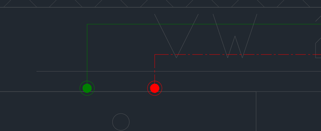
A connector is the point where a pipe is to start or end – for example cold and hot water of a lavatory. Its marker (disk and ring) has the color of its system. Connectors are created in three ways: free from a connector template (Inserting connectors), with a 2D fixture from the Block Library (Fixtures), and at every outlet of a manifold.
- If a pipe starts at a connector, it takes the connector's system (the palette changes). If it ends at a connector, the run ends there.
- If the connector has another system of the same role (for example cold water mains pressure instead of reduced cold water), Piping 2D asks: adapt the connector, adapt the whole pipe, or ignore.
- A connector of another role is never connected – the command line says so.
- Connectors have no elevation in 2D; an offset from a Piping 3D template only takes effect when converting to 3D.
Symbol in the pipe
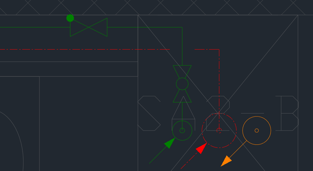
A symbol – ball valve, valve, backflow preventer, pump … – sits in a gap of the pipe: it divides the pipe, the gap is as long as the symbol (default 150 mm from connector to connector), and its line drawing sits in it, in the color and on the layer of the system. A symbol with a branch (three-way valve) has three connectors; a symbol with one connector (outlet, gauge) hangs at an open pipe end. If you delete the symbol, the pipe becomes one again. When converting to 3D the symbol becomes a valve.
Manifolds and PEX pipes
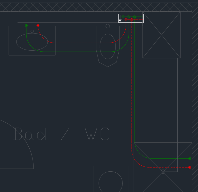
A manifold (plumbing floor manifold) has outlets in one system or two systems mixed, a supply inlet and optionally a cabinet. Each outlet and the supply inlet act as connectors. PEX pipes are flexible pipes from an outlet to the connector of a 2D fixture; each remembers its outlet so that it is not assigned twice. It is the same manifold as in Floor Heating.
Piping 2D and Piping 3D
| Piping 2D | Piping 3D | |
|---|---|---|
| Pipe | line or polyline with pipe data, elevation 0 | routing line with elevation, then 3D solids |
| Elevation | none – only the system elevation as a property | elevation or system elevation |
| Size | size in mm, optional | nominal size (DN) from the catalog |
| Catalog, manufacturer | none | catalog, product line, fittings |
| List | bill of materials with counted fittings | parts list and bill of materials |
| IFC | none | yes |
From a finished 2D plan Piping 3D creates a 3D plan: Converting 2D to 3D. The system elevations become elevations, the symbols valves, the risers vertical risers.
2D objects and CAD commands
Pipes, rise/drop symbols, symbols, connectors, elevation change circles, elevation symbols and manifolds behave like CAD objects: grips, MOVE, STRETCH, ROTATE, MIRROR, COPY and the Properties palette work. When the command ends, Piping 2D updates everything attached – in the same undo step:
- The neighbors of a moved pipe are shortened, extended or joined again – like Move in the palette. An end dragged alone takes along the ends that were attached to it.
- An elevation change circle, a symbol and the elevation symbols follow their pipe; pipes at a moved riser, connector or manifold follow it.
- A pipe broken at crossings of which only one piece was moved becomes one pipe again; the gaps are then created anew.
- Copies do not pull anything along. If a part is on a locked layer, Piping 2D changes nothing and reports it.