
Basic concepts
Once you know these terms, you understand every function of Piping 3D. The tasks refer back here whenever a term matters.
Routing line, 3D placed and fitting
On the Pipe page of the palette, Insert as decides what the next Insert creates. There are three ways:
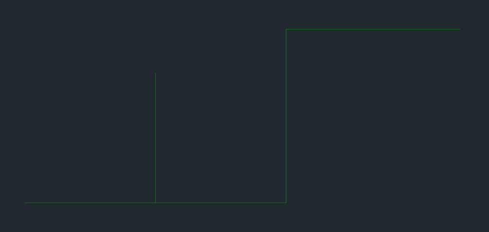
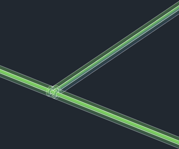
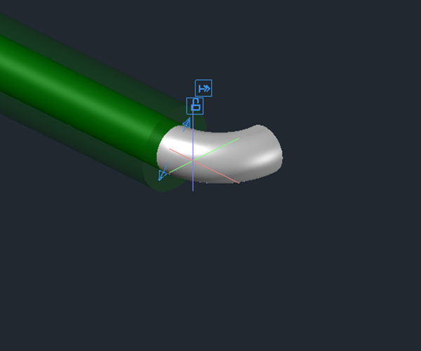
| Routing line | 3D placed | Fitting | |
|---|---|---|---|
| What is created | Only the routing line: the axis with all values (system, catalog, DN, insulation, elevation). | The routing line and on it pipes, elbows, tees and reducers from the catalog. | A single part: pipe, elbow, tee, reducer or coupling. |
| When to choose it | For planning and trying things out: fast, easy to change, clear in the plan view. | When the route is settled and you want to see the finished piping right away. | When a single spot is to be built by hand, for example an elbow at a certain distance. |
| 3D | Later with Generate 3D – for one pipe, one network or everything in a selection window. | Immediately, already visible at the cursor. | Immediately; pipes are created in between when you pull the part away. |
| Changing it | At the line: grips, Stretch, Move, elevation. | Also at the line – the grips of a pipe drag the line underneath, the 3D follows. | The part belongs to its pipe and moves along when the pipe changes. |
3D placed and Generate 3D give the same result: once while drawing, once afterwards. Such a pipe is called a pipe with 3D.
"3D placed" also creates a routing line
There is always a routing line underneath every pipe – even if you drew it with 3D right away. It is hidden while the pipe has 3D and carries all values of the pipe. That is why the rule for every pipe is: you change the line, the 3D follows.
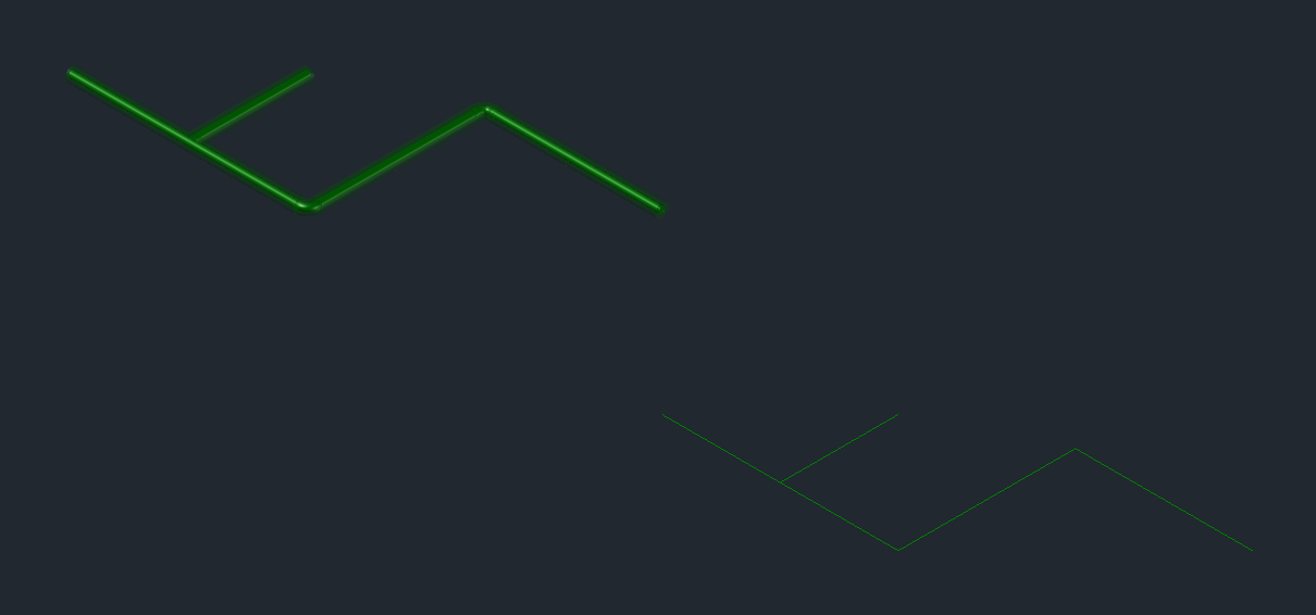
- Delete 3D removes pipes and fittings – the routing line stays and becomes visible again.
- Delete removes the pipe completely: line and 3D.
- A grip on a pipe drags the line underneath; at the end of the command the affected area gets its 3D again.
System
The system says what flows in the pipe: cold water, hot water, recirculation, heating supply and return, gas … It sets the color, the layer and the catalogs on offer. You manage systems in the gear menu › System definitions; each system has a short code and a name, for example "PWC-Cold water".
- Pipes only connect to pipes of the same system. A pipe of another system under the cursor is only a reference point while drawing.
- N at the cursor matches the system of a pipe you click.
Elevation and system elevation
Every pipe lies at an elevation (Z). On the palette you choose under System elevation how you enter it:
| Way | Meaning | Example |
|---|---|---|
| absolute | The elevation above project zero. | 3250 |
| from level | A level, a reference level and a distance. | 2nd floor, FF + 1000 |
| system elevation | A named elevation of a level from the gear menu › System elevations. | "Plumbing ceiling" |
| free | The elevation comes from the point you click – with object snap, the elevation of a part. | Click on a pipe end |
The reference levels of a level:
| Reference level | Meaning |
|---|---|
| TOS | Top of slab – the slab below, without flooring |
| FF | Finished floor |
| FC | Finished ceiling (for example a suspended ceiling) |
| BOS | Bottom of slab – the structural slab above |
Catalog, product line and nominal size
The catalog decides which pipes and fittings the pipe is built from: a manufacturer catalog, a building-services product line, or process piping with pipe specs. Below it you choose the product line (in process piping the pipe spec) and the nominal size (DN).
- Pipe variant, Elbows, Tees: these rows only appear when the catalog offers several versions. The pipe remembers your choice.
- Installation "flexible" (only for pipe on coils): corners are bent; fittings exist only at the start, at the end and at tees.
- Insulation: the thickness comes from the insulation table (gear menu) per system and nominal size; whether it is shown as a body you switch under Display.
Network and riser
Pipes of the same system that are connected form a network. Many functions act on the whole network: Generate 3D and Delete 3D, item numbers, the isometric, the flow direction and "Per network" for lists.
A riser is a vertical pipe that appears in the plan view as a rise/drop symbol (circle with arrow). A riser template describes several pipes side by side – for example cold water, hot water and recirculation – with spacing, DN and insulation. Risers or parallel pipes are created from it.
Connector
A pipe connector is a point where a pipe is to start – with system, DN and elevation. There are free connectors (for example for a fixture that is not drawn yet) and the connectors of fixtures from the Block Library and of custom parts. A pipe that starts at a connector takes over its system and its DN.
What "Generate 3D" does
Generating 3D means placing the parts from the catalog on the routing lines of a network.
- Pipes in stock length (the manufacturer's supply length or your own length), with a coupling from the catalog in between if set so (gear menu › Pipe settings).
- Elbows at corners, tees at branches, reducers where the DN changes – as the catalog offers them. If it has several suitable parts, LuaCAD asks (Fitting selection dialog box) or uses your choice stored at the pipe.
- Item numbers are assigned automatically.
- If something does not fit (a piece of pipe too short, a fitting the catalog does not offer), an issues list appears after the command, with "Show" for each spot.
Parts placed by hand
Everything you place on a pipe yourself instead of letting Generate 3D do it: a fitting by hand, a valve, a product, a custom part. Parts placed by hand belong to their pipe: they move along, appear in the isometric, the parts list and the PCF, and stay when the 3D is generated again.
Inserting in-line
A part is inserted in-line: the pipe is interrupted at that point and ends at the connectors of the part. This is how valves, symbols, products, custom parts, reducers and couplings get into a pipe – also into a pipe with 3D; then only the area around the part is rebuilt. An in-line part has a grip in its middle that slides it along the pipe.
Pipes and CAD commands
Routing lines behave like CAD objects: grips, MOVE, ROTATE, MIRROR, COPY and the Properties palette work. At the end of the command LuaCAD updates the adjacent pipes, the parts and the 3D – in the same undo step.
- A 3D body is never stretched: a stretched pipe snaps back; you change the length via the routing line (grip on the pipe or Stretch).
- What happens to the network when you select with CAD commands (ask, only the part, whole network) is set in the gear menu › Options › Editing.
- If a part lies on a locked layer, LuaCAD does not change it and says so.
The preview window
Piping 3D shows its 3D preview in the dialog box "Piping 3D - Add product" (or "Edit product") on the right under Preview – not in a floating window of its own. It shows the chosen article of the manufacturer catalog without its accessories, the way it will be inserted.
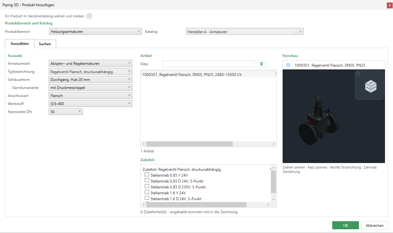
- When it changes: a moment after every choice in the article list. If an article has no body, it says "There is no body for this article".
- Use: dragging rotates, the wheel zooms, the cube chooses the view direction, the gear the visual style (wireframe to X-ray), view and view direction. There are no base points here – the product connects with its connectors when you insert it.
- The preview is part of the dialog: it opens and closes with it, there is nothing to show or hide.