
Fittings and custom parts
On the Fittings page you build what "Generate 3D" does not – mostly the vertical parts: stacks, double 45° bends, branch offsets. A part placed by hand stays when you generate the 3D again.
Manufacturer and product line
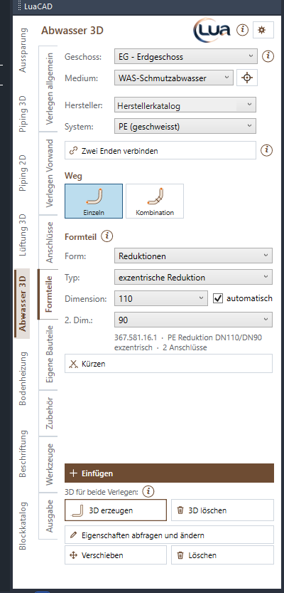
At the top you choose the manufacturer and the product line (the pipe product line, for example PE or a sound-insulated product line). The product line determines the fittings, the diameters and the stock lengths; its tooltip says what it is. By default the first manufacturer of the catalog with its first product line is set. This choice also applies to the diameter list "no standard" on the General routing page.
Single fitting
Goal: choose a single fitting from the catalog and insert it.
- Under Method choose the Single tile.
- Choose shape (elbow, wye, coupling, reducer …), type (within the shape) and size (outside diameter); 2nd size is the second diameter of a wye or reducer – for an elbow its angle is shown there.
- Below the lists the chosen part is described: article number, name, angle and number of connectors. The preview window shows it with its catalog bodies.
- Insert in the footer.
Options
- automatic (check box next to the size) – when connecting, the part takes the diameter of the free connector (then also with a different DN), on a pipe that of the pipe; inserted freely the chosen size applies. Default on.
- Without "automatic" the part connects only to the same nominal size (DN).
Combination
Goal: insert several matching fittings in one step – for example a double 45° bend.
- Under Method choose the Combination tile.
- Choose the combination:
| Combination | What is created |
|---|---|
| Branch offset wye-elbow | a wye with an elbow for a higher inlet |
| Branch offset elbow-elbow | two elbows for a higher inlet |
| Double 45° bend | two 45° elbows instead of one 90° elbow |
| Double 45° bend (88½°) | the same with 88½° in total |
| Wye-elbow 45° | a 45° wye with a 45° elbow |
| Wye-elbow 45° (88½°) | the same with 88½° |
- Spacing – the distance of the parts: fitting to fitting, manual (X dimension), 2 × inside diameter, 3 × inside diameter or fitting to fitting, shortened (inside diameter and "shortened" only for double bends). With "manual" the X dimension applies.
- Legs – which elbow legs the double bend uses: L-L (long-long), S-L, S-S – only for product lines whose elbows come in several leg lengths.
- Size (with "automatic" as for Single) and 2nd size – the diameter of the outlet, only for "Branch offset wye-elbow" and "Wye-elbow".
- Outlet – for the branch offset: where the outlet points after the elbow: parallel (0°), upward, 45° to the side, 90° to the side.
- Insert in the footer.
Inserting, connecting, inserting in-line
Goal: connect the chosen part to a free end, insert it in-line into a pipe or insert it freely.
- Insert in the footer (or double-click a tile). The part hangs at the cursor.
- Move it to a free end: it connects – the marker shows where. A part with a fixed size connects only to the same DN.
- Moved onto a pipe or a plumbing line, it is inserted in-line: first click the pipe, then slide along and click. The pipe is divided and connected as when connecting (fused with weld loss).
- With no end nearby it is inserted freely.
- Clicking places the part; the next one hangs at the cursor. Enter = done, Esc = cancel.
Keys at the cursor
| Key | Effect |
|---|---|
| F | hold at the marker |
| Z | pull away from the connector – a pipe is created in between; type a length and Enter. Back behind the connector shortens (at most the shortening of the catalog, never for push-fit). |
| Space | show the connectors of the part – click one, then it hangs at the cursor by that point |
| R | free at the cursor rotate with the mouse; connected to the next arm |
| D / W | type an angle / pick it with two clicks |
| Arrow keys | rotate by 90° |
| A | free at the cursor: distance to a reference point (amounts X/Y, base point in the dialog box) |
| N | take over the system of a clicked pipe (the click inserts nothing) |
Options
- Connect timer (gear menu › Options › Snapping) – if the part stays at a connector this long, it is held as with F. Default off.
- Ask when connecting to a different system (gear menu › Options › Snapping, default on) – if the connector belongs to a different system than on the palette, LuaCAD asks "Connect" or "Cancel". "Remember answer" switches the question off.
- Snap to objects within (gear menu › Options › Snapping, default 5 cm) – how close to a connector the part snaps.
- The base point: click a grip in the preview window – the part hangs at the cursor by it.
Shortening a fitting
Goal: shorten a free connector of an inserted fitting as far as the catalog allows.
- Click Shorten (under Single).
- Click a free connector of a fitting – it is fully shortened.
- Clicking again cancels the shortening.
Push-fit fittings cannot be shortened; at an outlet only so far that the cut does not lie in the run.
Connecting two ends
Goal: connect two free ends facing each other with a pipe, an offset or a reducer.
- Click Connect two ends.
- Click the free end you connect from (1) – it sets product line, system and level.
- Click the opposite free end (2). Esc = back to the first end.
- The solutions appear in color (3): pipe, offset with two elbows, with a reducer for different DN. Tab or arrow right/left switches, the yellow one is selected; if none fits, the reason is in the command line.
- A click or Enter applies, Esc discards. Then the next pair right away; Enter = done.
Inserting a custom part
Goal: insert a part from a DWG – for example a floor drain or a roof drain – and connect it to the pipe.
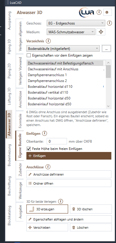
- Custom parts page: choose a folder under Folder. … adds folders, renames or removes them (network folders too). By default "Examples / special parts" and the supplied floor drains are there (read only).
- Choose a part in the list – its picture appears below. The list shows only DWGs with at least one connector; how many without a connector are hidden is shown below.
- Insert (or double-click in the list). The part hangs at the cursor by its insertion point.
- The Space chooses a connector: then it connects to pipes and fittings of the same DN (F holds, Z pulls away with a pipe). With two aligned connectors it is inserted in-line into a pipe. Otherwise it is inserted freely.
- Enter = done.
Options
- Top edge – the elevation of the top edge (insertion point) above the finished floor (FF) of the level, for inserting freely; default 0.
- Fixed elevation when inserting freely – checked (default), the top edge lies at the elevation above when inserted freely; unchecked, at the elevation of the cursor. When connected, the elevation of the connector always applies.
- Show properties before inserting – the property fields of the part (manufacturer, article number …) before the cursor; default off.
- Show in folder, Open folder – open the folder in Windows Explorer. If the chosen DWG has no connector, Open part and Show in folder appear with a message.
More on managing the folders: Custom parts.
Defining the connectors of a custom part
Goal: give a DWG connectors so that it can be connected.
- Open the DWG (Open part or as usual).
- Define connectors – the custom part wizard runs in the open DWG.
- Place a colored circle for every connector, diameter = DN: light blue = socket, dark blue = spigot end, red = fused.
- Save – the part appears in the list.
The wizard also enters manufacturer, article number and further values; which fields exist is set in the gear menu › Properties › "Property fields …". The wizard in detail: Defining connectors.