
Floor Heating
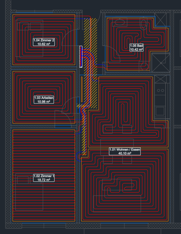
With Floor Heating you lay out a floor heating system in plan view (2D): you draw the rooms, LuaCAD derives the heated areas from them and lays the loops inside – as a counterflow or serpentine pattern, with supply and return, perimeter zone and the minimum bend radius of the pipe. On top come the manifolds with their outlets and the leaders from the manifold to every loop – automatically as an orderly bundle along the walls, through a leader corridor in the hallway, or drawn by hand. Room tags, loop texts, the loop schedule and the bill of materials come from the same data.
Everything is linked: when a room changes, its heated areas and loops are rebuilt automatically, and the leaders follow. Whatever you adjust by hand stays that way until you set it back to "automatic". The plug-in works in plan view only – there is no 3D.
How this help is organized
From the big picture to the details – read only as far as you need right now:
| Part | What you find there | For whom |
|---|---|---|
| Quick start | A room with a loop, a manifold and leaders in a few steps – one picture per step – and the first changes. | Anyone drawing their first floor heating system today |
| Concepts | Room, exclusion area, heated area, loop, counterflow and serpentine, perimeter zone, manifold and outlet, leader, leader corridor, "automatic" and "by hand". | Anyone who wants to understand how the plug-in works |
| Tasks | Every function of the palette and of the bar at the cursor in detail: goal, steps, keys, options, example, notes – with a short video at the end. | Anyone who needs a particular function |
| Reference | All buttons per palette page, all keys, the gear menu, the dialog boxes, every setting in detail and the typical messages. | Anyone looking up something specific |
The tasks follow the pages of the palette: Rooms, Heated areas, Loops, Manifold, Leaders, Editing with the tools and Output.
Overview
This is how a floor heating system comes together, step by step:
- Create the rooms – as a rectangular outline, from a polyline or corner by corner. Number, name and room temperature are set in the palette; the room tag comes along right away.
- Generate the heated areas: the area is the room, offset inward by the edge distance. Use an exclusion area for a shaft or a kitchen counter, and divide large rooms.
- Place the loops: click the heated area, choose the connector point – the counterflow or serpentine pattern is created automatically.
- Insert the manifolds: the loops get their outlets ("1.03" = manifold 1, outlet 3).
- Leaders: connect all loops of a manifold at once, add individual ones later, or draw them by hand.
- Output: room tags and loop texts, loop schedule and bill of materials.
| Page | What you find here |
|---|---|
| Rooms | Values of the next room, rectangular room, from polyline, pick points, change room, room tag, delete room, check rooms, editing rooms with GstarCAD |
| Heated areas | Edge distance, generate heated areas, for all rooms, divide area, join areas, exclusion areas |
| Loops | Values of the next loop, place loop, maximum loop length, connector point, perimeter zone, change, delete, automatic again |
| Manifold | Next manifold, insert, change, flip outlet side, delete, assign loops, assign by hand, manifold options |
| Leaders | Draw by hand, single, edit with grips, move, cross and swap, leader corridor, all loops of a manifold, individual loops, insulation layer |
| Editing | The tools below every page: properties, delete, add and remove vertex, move segment and corner, automatic again, check, working with the GstarCAD commands |
| Output | Loop schedule, bill of materials, list options, lists across several drawings, update lists, annotate, loop text and coloring |
The pages of the palette
Open the palette from the ribbon › tab LuaCAD › Floor Heating; how a palette is laid out is explained in Getting started. Every page has an "i" at the top with a short explanation; "More in the online help" leads to the sections here. Every button of a page is listed in the Reference, every setting under Every setting in detail.
Highlighted buttons (in the color of the plug-in) insert something new into the drawing. The same Tools sit below every page. Values in the palette apply to what you insert from then on.
Rooms
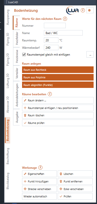
Every floor heating system starts here. A room is a closed outline with number, name and room temperature; its heated areas and the loops inside are derived from it. At the top are the values for the next room, below them the three ways to insert a room and the buttons for editing.
Tasks on this page: Values for the next room · Rectangular room · Room from polyline · Pick room · Change room · Room tag · Insert / reposition room tags · Delete room · Check rooms
Heated areas
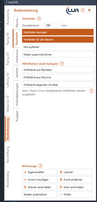
A heated area is the part of the room where the pipes lie: the room, offset inward by the edge distance. Exclusion areas (shaft, kitchen counter, built-in closet) stay free. You can divide a large room into several areas – each gets its own loops.
Tasks on this page: Edge distance · Generate heated areas · For all rooms · Divide area · Join areas · Exclusion areas
Loops
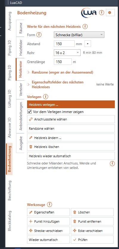
A loop is the pipe from the manifold (supply) through the area and back (return). At the top are the values for the next loop – pattern, on-center spacing, pipe, maximum loop length, perimeter zone – below them Place loop and the buttons for adjusting a placed loop.
Tasks on this page: Values for the next loop · Place loop · Maximum loop length · Choose connector point · Choose perimeter zone · Change loop · Delete loop · Loop automatic again
Manifold
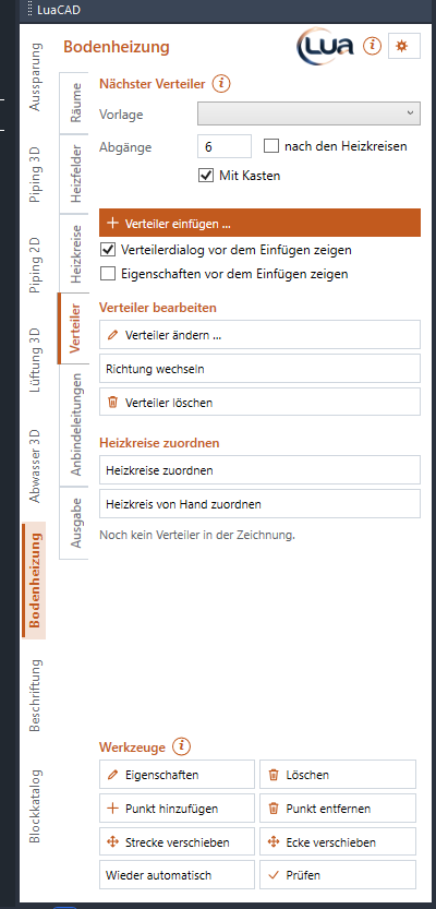
The manifold distributes the heating water: one outlet with supply and return per loop, with or without cabinet. By default it gets as many outlets as there are loops on it. A new loop automatically gets a free outlet of the nearest manifold; Assign loops redistributes all of them so that nothing crosses.
Tasks on this page: Next manifold · Insert manifold · Change, flip, delete · Assign loops · Assign by hand · Manifold options
Leaders
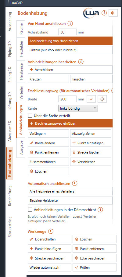
Leaders carry supply and return from the manifold to the loop; their length counts toward the loop. By hand you draw them yourself, corner by corner. Automatically they run bundled along the wall or along a leader corridor and follow on their own when a loop is re-placed or the manifold is moved. Connecting never changes loops or heated areas.
Tasks on this page: Draw by hand · Single · Edit with grips · Move · Cross and swap · Insert leader corridor · Edit leader corridor · All loops of a manifold · Individual loops · Insulation layer
Output
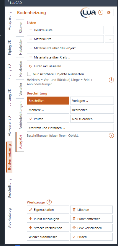
The loop schedule (per loop: room, area, spacing, lengths; grouped per manifold with subtotal) and the bill of materials (heating pipe with coils, manifolds, edge insulation strip) as a table in the drawing or as a file, also across several drawings. Annotations are attached to the room, the loop or the manifold and follow it. The plug-in has no IFC export.
Tasks on this page: Loop schedule · Bill of materials · List options · Across several drawings · Update lists · Annotate · Annotate several · Loop text and coloring
Tools (below every page)
You see the footer at the bottom of every picture of a palette page: two columns of small buttons – Properties and Delete, Add vertex and Remove vertex, Move segment and Move corner, Automatic again and Check; the "i" next to the title explains them.
Properties, Delete and Automatic again act on the object you click (room, heated area, loop, leader, manifold). Add/Remove vertex, Move segment and Move corner apply to loops and leaders: corners get the bend radius, the partner (supply or return) follows at its distance where that is unambiguous; afterwards the loop is "by hand".
Tasks in this footer: Properties · Delete · Add vertex · Remove vertex · Move segment · Move corner · Automatic again · Check
Keys at the cursor
During a function the bar at the cursor shows all keys that apply right now – to click or to press. The same key means the same thing in every plug-in; the full list is in the Reference.
| Key | Meaning |
|---|---|
| A | manifold: distance to a reference point; leader by hand: spacing increment and wall offset; leader corridor: width and wall offset; move, vertex and corner: type a distance |
| Space | leader by hand: 90° / 45° / free in turn; leader corridor: angle increment on/off; manifold: switch the base point |
| V | while drawing: round the length of every segment to the spacing increment (on/off) |
| F | leader by hand: connect to the loop now |
| I | leader by hand: continue with supply or return only from here |
| S | leader by hand: the pair to the other side; manifold: outlet side front/back |
| R, D, W | rotate the manifold, type an angle, pick an angle (two clicks) |
| M | manifold: mirror (top/bottom, left/right) |
| ← / → / ↓ | leader corridor: the clicked line is the left edge, the right edge or the center |
| Backspace | leader corridor: last point back |
| Enter | finish or accept |
| Esc | cancel – while drawing, the placed segments stay |
The Help button in the bar opens the help for the running function.