
Ventilation 3D
With Ventilation 3D you design air distribution systems in 3D: rectangular ducts, round (spiral) ducts and flexible ducts, plus dampers, sound attenuators, grilles, air valves, fans, manufacturer products and custom parts such as air handling units. Unlike Piping 3D there is no routing line: you draw the duct run point by point, and LuaCAD inserts the solids right away – straight duct pieces, elbows, reducers and transitions from the chosen catalog.
How this help is organized
From overview to detail – read only as far as you need right now:
| Part | What you will find | For whom |
|---|---|---|
| Quick start | Insert and edit a simple duct in a few steps – one picture per step. | Anyone drawing their first duct today |
| Concepts | Duct run and fitting compared; duct, round duct and flexible duct; system, catalog, justification, duct network and duct section, connector, inserting in-line, elevation change. | Anyone who wants to understand how Ventilation 3D works |
| Tasks | Every function of the palette and of the action bar in detail: goal, steps, keys, options, example, notes – with a short video at the end. | Anyone who needs a particular function |
| Reference | All buttons per palette page, all keys, the gear menu, the dialog boxes and every setting in detail. | Anyone looking for something specific |
The tasks are ordered by work step: Drawing ducts and round ducts, Flexible ducts, Duct accessories, products and custom parts, Editing parts, Tools and Output.
Overview
A duct network is created step by step:
- On the Parameters page choose catalog and material – by default "EN 1505 / EN 1506 (made to measure)", fabrication by the sheet metal contractor. These values apply to all new ducts and round ducts.
- On the Ducts page choose the system (supply air, exhaust air …), the size A × B, the insulation and the elevation.
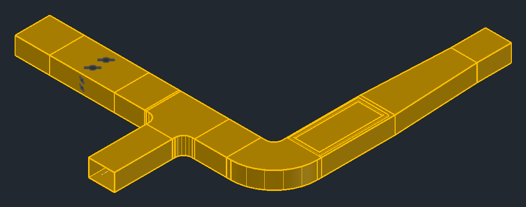
- Click Insert and click the duct point by point into the drawing – elbows, reducers and transitions are added by themselves.
- Add round ducts, flexible ducts to the outlets, duct accessories and products – see Inserting a round duct, Inserting a flexible duct and Inserting a part in-line.
- Change things with grips, Move, Move elevation and properties – see Editing parts.
- Output item numbers, parts list and bill of materials, annotation and dimensions – see Output.
| Page | What you will find |
|---|---|
| Drawing ducts and round ducts | Duct run, round duct run, fitting by hand, connecting two connectors, duct sizer, picking values |
| Flexible ducts | Inserting a flexible duct, editing vertices and segments, joining, flattening |
| Duct accessories, products and custom parts | Inserting parts in-line or surface-mounted, setting up duct accessories, manufacturer products, custom parts and their connectors |
| Editing parts | Selecting, grips, Move, Move elevation, properties, Segment, Delete, levels |
| Tools | Picking the base angle, clashes, insulation, fabrication parameters, checking the duct network |
| Output | Item numbers, lists, fitting symbols, annotation, dimensions, IFC |
The pages of the palette
Open the palette on the ribbon › LuaCAD tab › Ventilation 3D; how a palette is laid out is explained in Getting started. Each page has an "i" at the top with a short explanation; "More in the online help" leads to the sections here. Every button of a page is listed in the Reference, every setting under Every setting in detail.
On the pages Ducts to Custom parts the same rows System and (except for round ducts) Justification are at the top, and Insulation (where the part is insulated), Elevation and the buttons to insert and change parts are at the bottom. Each page remembers its own justification and insulation.
Parameters
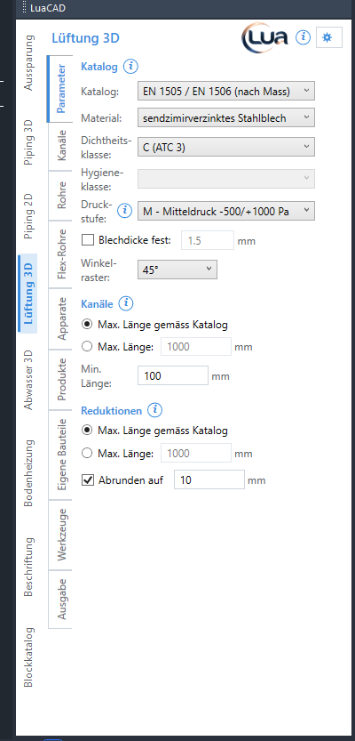
Here you set what new ducts and round ducts are made of: catalog (by default EN 1505 / EN 1506 made to measure, or a manufacturer catalog), material, air leakage class and hygiene class, and in the made-to-measure catalog also the pressure class and the sheet thickness. Below are the angle increment for drawing, the maximum length of straight duct pieces ("Ducts") and how long reducers become ("Reducers"). Existing parts do not change – use fabrication parameters for that.
Tasks on this page: Catalog and classes · Dividing into pieces by maximum length · Angle increment · All settings of this page
Ducts
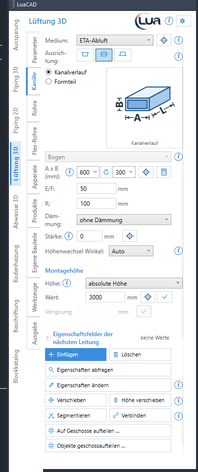
Rectangular ducts: with Duct run you draw a whole run point by point, with Fitting you insert a single part from the catalog (elbow, tee, offset, wye, takeoff …). The fields show only the dimensions the chosen part needs; the picture on the right shows where they are, and the preview window shows the fitting in 3D. Insert starts in the drawing; the buttons below change what is already there.
Tasks on this page: Inserting a duct · Inserting a fitting · Connect · Duct sizer · Picking values · Query properties · Change properties · Move · Move elevation · Segment · Delete · Divide across levels
Round ducts
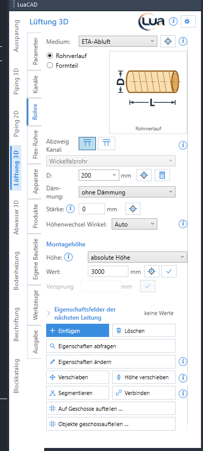
Like the Ducts page, but for round ducts (diameter D instead of A × B). Under Branch to duct you choose how a round duct joins a rectangular duct: through a tee with transition or through a takeoff in the duct side. Flexible hoses are on the Flexible ducts page.
Tasks on this page: Inserting a round duct · Inserting a fitting · Connect · Duct sizer · Editing parts
Flexible ducts
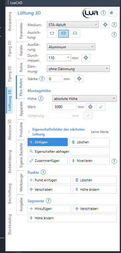
A flexible duct runs as a smooth curve through the points you click; at an open round connector it connects and takes over diameter and system. With the buttons under Vertices and Segments you change an existing flexible duct. Only the aluminum type is insulated.
Tasks on this page: Inserting a flexible duct · Editing vertices · Editing segments · Join and Flatten
Duct accessories
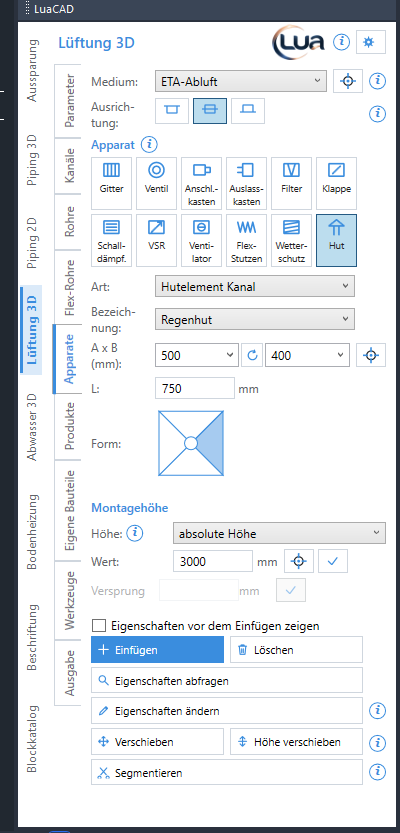
Dampers, grilles, filters, fans and other accessories made to measure. Choose the symbol at the top, then the type (for duct or round duct) and the designation; below are only the dimensions this accessory needs. Devices the air flows through (damper, sound attenuator, fan …) are inserted in-line in a duct; grilles and air valves sit on the duct side.
Tasks on this page: Setting up a duct accessory · Inserting a part in-line · Placing a grille, air valve or takeoff · Moving an in-line part
Products
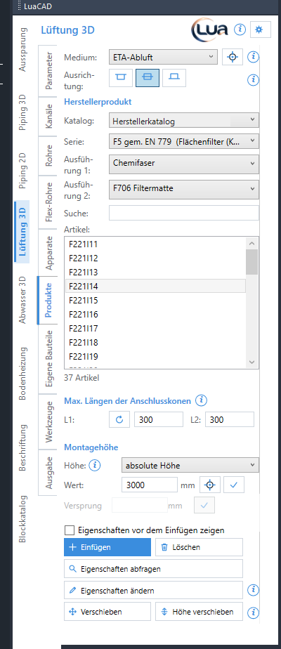
Articles from manufacturer catalogs – for example fire dampers, dampers and airflow regulators, sound attenuators, filters or air terminals. Choose catalog and series, narrow down with the variants and the search, choose an article and click Insert (or double-click). The order number goes into the lists.
Tasks on this page: Inserting a manufacturer product · Inserting a part in-line
Custom parts
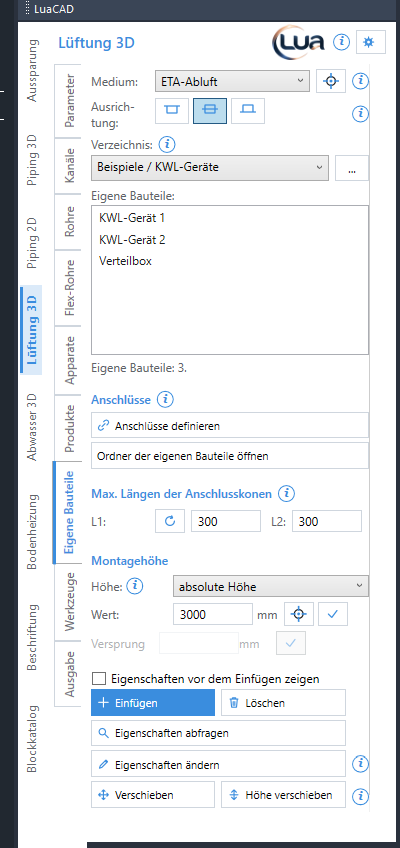
A custom part is your own DWG or DXF, for example an air handling unit. To connect to ducts it needs connectors ("Define connectors"). By default the examples "Air handling units" and "Residential ventilation units" are in the list.
Tasks on this page: Inserting a custom part · Defining connectors
Tools
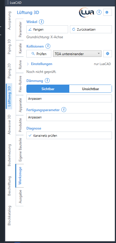
Check what is already inserted and change many parts at once: align the angle increment with a skewed wall, look for clashes, show, hide or change insulation solids, swap catalog and material of many parts, check the duct network for open ends and gaps.
Tasks on this page: Picking the base angle · Checking for clashes · Showing and adjusting insulation · Adjusting fabrication parameters · Checking the duct network
Output
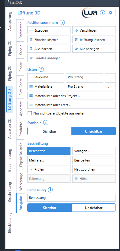
Item numbers, parts list and bill of materials (as a table in the drawing or as a file, also across several plans), fitting symbols in plan view, annotation from templates and the duct size dimension. The IFC export is on the ribbon › LuaCAD tab › Exchange ribbon panel.
Tasks on this page: Item numbers · Parts list · Bill of materials · Across several plans · Fitting symbols · Annotating · Dimensions
Keys at the cursor
While a function runs, the action bar at the cursor shows every key that currently applies – to click or to press. The same key means the same thing in every plug-in; the complete list is in the Reference.
| Key | Meaning |
|---|---|
| A | before the first point: distance to a reference point; during the run: elevation and wall offset; connected: length of the pull |
| Space | during the run: snap to angle / free; at a part: show the base points |
| W | pick an angle (two clicks) |
| D | type an angle |
| R | rotate – with the mouse, or to the next arm |
| F | hold at the connector, or release |
| Z | pull away from the connector – a straight piece is created in between |
| P | match properties (size, system, catalog) of a clicked part |
| N | match only the system |
| K | the next reducer centered, flush left or flush right |
| B | reference point for typed coordinates |
| ← / → / ↓ / ↑ | during the run: draw along the left or right side of the duct, center, new centerline |
| Enter | finish |
| Esc | cancel – during a run the placed parts stay |
The Help button in the bar opens the help for the running function.