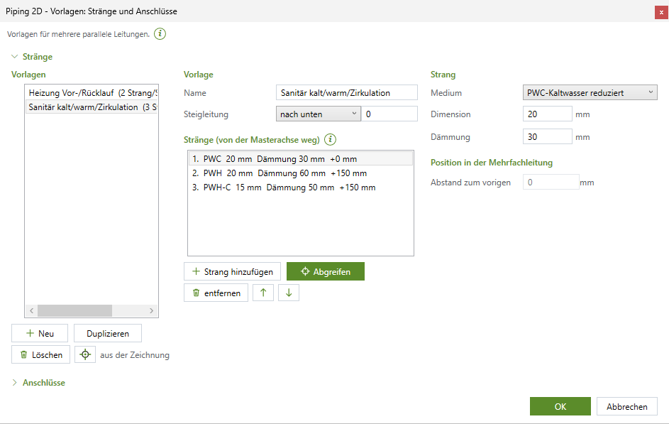
Highlighted buttons (in the color of the plug-in) insert something new into the drawing; all others change what is already there. Every button shows a tooltip when you hover over it. A Pick button takes a value from the drawing.
The same key means the same thing in every plug-in. Which one applies right now is shown by the action bar at the cursor; Shift and Ctrl are never used at the cursor (they belong to the CAD).
Key
Meaning in Piping 2D
A
before the first point (pipe, parallel pipes, riser, connector, manifold): distance to a reference point; while drawing: system elevation, wall offset and fixed length; Move: a distance or the wall offset to the pipe at the cursor
Space
while drawing: snap to angle / free; riser row: next riser at the cursor; connectors and manifold: switch the base point; Move: free or next pipe
W
pick an angle – always two clicks
D
type an angle (degrees)
R
riser row by 45 degrees, rotate connectors and manifold
S
parallel pipes: side of the risers; manifold: outlet side front/back
M
manifold: mirror in turn top/bottom, left/right
P
while drawing: match the properties of a pipe; parallel pipes before the first point: pick pipes
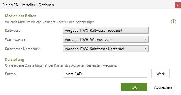
Which system has which role at the manifold, look of the cabinet – see Manifold options.
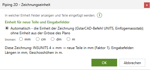
Settings › Drawing units …
In which units new parts are created and fields show lengths – for all plug-ins.
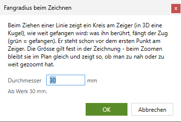
Settings › Snap radius when drawing …
How close the cursor has to come to a pipe for the run to snap – shown as a circle at the cursor.
Properties › Property fields …
Which fields exist (default fields, your own fields) – for all plug-ins.
Properties › Property fields of a pipe …
Click a pipe – the fields of its network.
Properties › Author …
The name in outputs – for all plug-ins, empty by default.
Layer › Create all layers of this plug-in
Creates missing layers; existing ones stay as they are.
Help › Help
This online help.
Help › Info
Version and program components.
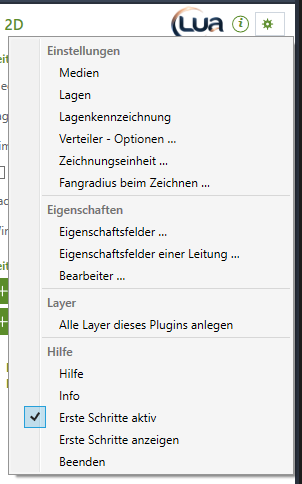
Help › Getting started active
Cards of the pages and insertion help for this plug-in on or off.
Help › Show getting started
The tip wizard guides through the page shown; all pages show their tips again afterwards.
Help › Exit
Close the palette – open it again from the ribbon.
The LuaCAD settings (for all plug-ins) are on the ribbon › LuaCAD tab › Info – see Getting started. Piping 2D has no levels and no elevation values; the system elevations are the system elevations of the drawing.
Picture coming soonThe System elevation and wall offset while drawing dialog box: short line with "i" (1), system elevation (2), wall offset with value and side (3), Next segment: fixed length (4)
Opens while drawing a pipe or parallel pipes with A; applies to the running insertion only.
The system elevation from the next click; an elevation change circle is created at the corner. If there are no system elevations, a note says so (gear menu › System elevations).
Wall offset
Value and side (left, right in drawing direction, none) – the pipe runs at this distance next to the drawn line, in this run only.
Fixed length
0 = drag with the mouse; otherwise after OK a segment of this length is inserted in the current direction.
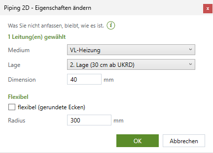
The Properties dialog box for one selected pipe: header (1), system and system elevation (2), size (3), Flexible (4); with risers and connectors the Risers rows and the connectors on the right are added
Tools › Properties, or Edit riser/connectors on risers. ONE dialog box for pipes, risers and free connectors; it shows only the rows that fit the selection. What you do not touch stays.
Field
Applies to
Effect
Header
–
"n pipe(s) selected", "n pipe(s) and m riser(s) selected" or "m riser(s) selected".
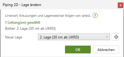
The Change system elevation dialog box: header (1), Current (2), New system elevation with Pick button (3)
Tools › Change system elevation. At the top "n pipe(s) selected" and "Current: …" (the system elevation of the selected ones, "various"). New system elevation: the one from the palette is proposed; "(no system elevation)" removes it. The Pick button closes the dialog box, lets you click a pipe and shows the dialog box again with its system elevation.
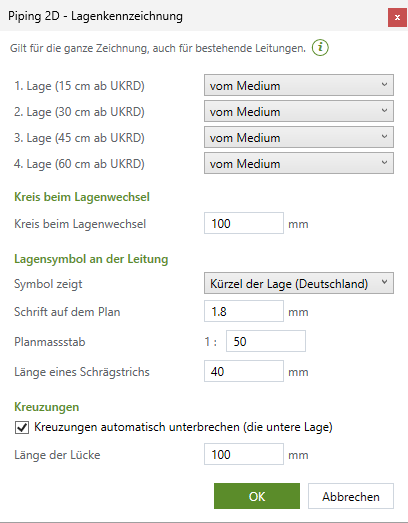
The Elevation marking dialog box: the linetype per system elevation (1), circle at elevation change (2), elevation symbol at the pipe (3), crossings (4)
Gear menu › Elevation marking. Applies to all drawings; after OK also to the existing pipes of the active drawing. If there are no system elevations, a note at the top says so. Every setting: Gear menu › Elevation marking.
The Systems dialog box: the system list (1), Edit (2), under plug-ins Piping 2D is selected (3)
Gear menu › Systems. The system definitions with the own entry of Piping 2D: an own list (taken over from Piping 3D at the first start) with its own display. Two entries per system:
Entry
What it draws
single-line (2D pipe)
Pipes, rise/drop symbols, manifolds and symbols of Piping 2D – layer, color, linetype, lineweight; independent of the display in Piping 3D.
riser insulation circle
The second circle of an insulated riser – color, layer and linetype of its own.
Double-click edits a system, OK saves. A change "by layer" goes to the layer of the current drawing. More under System.
The System elevations dialog box: the system elevations (1), Edit, Add, Remove, Duplicate (2), Load from template, Save as template (3)
Gear menu › System elevations. The list shows per system elevation "abbreviation [distance in cm above/below reference level]", the higher ones first. Edit opens per system elevation abbreviation, name, reference level and distance. After OK the existing pipes of the drawing follow (renamed abbreviations, linetype, elevation symbols, elevation table, crossings).
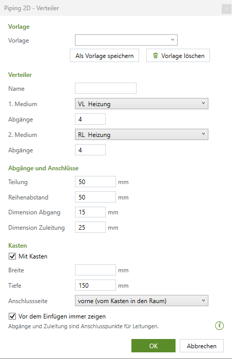
The manifold dialog box: template with Save as template and Delete template (1), name (2), 1st system and outlets, 2nd system and outlets (3), outlet spacing, row spacing, outlet size and supply inlet size (4), With cabinet, width, depth (5), outlet side (6), Always show before inserting (7)
Comes before inserting (with the check box "Show the manifold dialog box before inserting") and with Change manifold …. The values apply to the next manifold or the clicked one; with OK it hangs at the cursor. Every setting: Manifold dialog box.
The Manifold options dialog box: systems of the rows (1), display of the cabinet with Default (2)
Gear menu › Manifold options …. Systems of the rows: the system per role – applies to all drawings. Display: the look of the cabinet. Every setting: Manifold options.
The Templates: risers and connectors dialog box: templates (1), name, direction, riser height, risers (2), values of the riser (3), connector templates, collapsed here (4)
Risers/connectors page › "…". The risers at the top, the connectors at the bottom; the section of the selected group is open. OK saves both. The same dialog box in "one template" mode is the check before inserting (title "Insert riser", "Parallel pipes" or "Insert connectors"): changes apply to this insertion only, the template stays; Esc at the cursor returns there. Every setting: Templates.
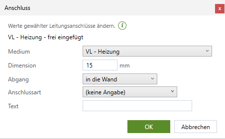
The 2D connector dialog box of a freely inserted connector: system (1), size (2), outlet direction (3), end type (4), text (5); x and y only appear for a connector in a set
Edit riser/connectors … or Properties on free connectors or connectors of a 2D fixture. The 2D version has no elevation. Only what you enter is changed; empty fields stay as they are for all selected connectors.
A before the first point: the values X and Y to the reference point (for connectors and manifold also the base point in the 3 × 3 grid). The distance applies to all further parts of this command. See Inserting at a distance.
With the check box Show properties before inserting (Symbols and Manifold pages): the values go to every part you insert now; a tag is counted up. Esc at the cursor returns here. Afterwards change the values of a part in the Properties palette.
The Snap radius when drawing dialog box: diameter (1)
Dialog box
What it controls
Drawing units …
In which units new parts come into the drawing and fields show lengths: automatic, mm, cm, dm, m. Applies to all plug-ins – see Drawing units. The size is always in mm.
Snap radius when drawing …
The diameter of the circle at the cursor in the drawing (default 30 mm, 2 to 2000 mm): whatever it touches, the run snaps to. A pipe of another system never snaps in Piping 2D.
Here is every setting of Piping 2D – in the palette, the gear menu and the dialog boxes – with its effect, the default value and an example. Values in the palette apply only to pipes and parts you insert from now on and are saved right away; while a run is in progress they apply from the next segment. Settings in the gear menu apply to all drawings unless "per drawing" is noted. Type lengths in the unit of the field; every number field calculates ("600+400" becomes 1000). A "-" in the column "Default" means: the value depends on the data.
System of the next pipes – sets color and layer; only the systems of Piping 2D. The Pick button takes the system of a pipe. Change systems: gear menu › Systems.
System elevation of the next pipes – sets linetype and crossings; the same list as on the Risers/connectors page. The Pick button takes it. Create system elevations: gear menu › System elevations.
(no system elevation)
in the floor
Size
Size in mm, optional – for list, annotation, riser circles and conversion to 3D. Empty = none.
empty
20
flexible (rounded corners)
New pipes as a polyline with rounded corners.
off
on for PEX
Radius
Radius of the rounded corners; available only with "flexible". If it does not fit, a smaller one is used (red at the cursor).
300 mm
250 mm
Angle increment
free, 15°, 30°, 45°, 90° – the steps the pipe follows; Space switches between free and increment while drawing. W/D align its base direction.
45°
90° for right-angled plans
Property fields of the next pipe
Fields every new pipe receives (only those it does not carry yet).
Riser template or connector template for "Insert riser/connectors"; parallel pipes take the riser template chosen last. Both choices and the group are remembered.
the first riser template
cold/hot water with recirculation
Show the dialog box before inserting
Before risers, connectors and parallel pipes first the template in a dialog box – applies to this insertion only; off = straight to the cursor. The same as in Piping 3D.
on
off for fast work
Axis cross in the riser circle (this drawing)
Cross through every riser circle – per drawing, Piping 2D and 3D, also for existing risers.
The abbreviation of the system elevation – required, unique (regardless of upper/lower case); shown at the pipe, the elevation symbol and in the table.
D1
Name
Full name; in lists "abbreviation – name".
in the floor
Reference level
The reference level of the level from which the distance counts (TOS, BOS, FF, FC …).
FF
Distance
Distance from the reference level (from 0) – in 2D it only sets the order (which one lies on top), when converting the elevation.
50
Load from template / Save as template
Get the list from your settings or store it there.
Position relative to the insertion point: x along the wall, y into the room.
per template
−100 / 0
Connector › Outlet direction
The direction in which the pipe leaves the connector.
into the wall (−Y)
–
Connector › End type, Text
End type; free description (for example "angle valve").
per template
shower
The elevation above the system elevation of a connector template does not apply in 2D; it is kept for converting to 3D.
#Gear menu › Drawing units, snap radius, properties, layer, help
Entry
What it controls
Default
Drawing units …
Units of new parts and of the fields – for all plug-ins.
-
Snap radius when drawing …
Diameter of the snap circle at the cursor in the drawing (2 to 2000 mm).
30 mm
Property fields …
Which fields exist (default fields on/off, your own fields) – for all plug-ins.
–
Property fields of a pipe …
Click a pipe: the fields of its network.
–
Author …
The name in outputs – for all plug-ins.
empty
Layer › Create all layers of this plug-in
Creates missing layers (for example for an office template); existing ones stay. Change names, colors and linetypes in the GstarCAD Layer Manager – the assignment stays. The elevation table lies on LuaCAD_BES_Listen.
–
Help › Getting started active
Cards of the pages and insertion help for this plug-in.
Piping 2D does not create IFC - only after converting in Piping 3D.
IFC export with 2D pipes.
Convert in Piping 3D.
n inconsistency(ies) - details are in the log.
"Check" found something.
Read the log (LuaCAD_Gstar.log).
Drawing did not work / The tool did not work …
An unexpected error.
Repeat; otherwise send the log to support.
The size is not a number (or negative). · The radius must be at least 1 mm. · The fixed length is not a number (or negative).
Input error in the dialog box.
Correct the value.
The diameter must be greater than 1. · The text must be at least 0.5 mm high and the scale at least 1. · Text height, slash length and gap must be greater than 1.