
Floor Heating reference
The palette buttons
Highlighted buttons (in the color of the plug-in) insert something new into the drawing; all others change what is already there. Every button shows a tooltip when you hover over it. Almost every button runs in a loop: click the next object right away, Enter finishes.
Rooms page
| Button / section | Effect | More |
|---|---|---|
| Values for the next room: number, name, room temp., heat loss | Values of the next room. | Next room |
| Insert room tag right away, "..." | Every new room gets its tag; "..." = lines and shape. | Room tag |
| Rectangular room | Click two corners. | Rectangular |
| Room from polyline | Click a closed polyline; it stays. | Polyline |
| Pick room (points) | Corner by corner, Enter closes. | Points |
| Change room ... | Number, name, room temperature, heat loss, edge distance. | Change room |
| Insert / reposition room tags | Insert missing tags, put existing ones back in place. | Tags |
| Delete room | Room with heated areas, exclusion areas and loops. | Delete |
| Check rooms | Count and check – result in the command line. | Check |
Heated areas page
| Button / section | Effect | More |
|---|---|---|
| Edge distance | Distance of the area from wall and exclusion areas, for new rooms. | Edge distance |
| Generate heated areas | Click rooms – their areas are rebuilt (including parts by hand). | Generate |
| Heated areas for all rooms | All rooms of the drawing; parts by hand stay. | All |
| Divide area | Dividing line across the area. | Divide |
| Join areas | Click two areas – the division is removed. | Join |
| Rectangular exclusion area / from polyline / pick (points) | Spot without heating; the areas leave it out. | Exclusion areas |
Loops page
| Button / section | Effect | More |
|---|---|---|
| Values for the next loop: pattern, spacing, pipe, maximum loop length | Values of the next loop. | Next loop |
| Perimeter zone (closer at the exterior wall) | Choose when placing, width, spacing. | Perimeter zone |
| Property fields of the next loop | Values for every newly placed loop. | Property fields |
| Place loop ... | Click the heated area, then the connector point. | Place |
| Always show before placing | The dialog box with the values first. | Place loop dialog box |
| Choose connector point | Click the loop, then the spot at the edge. | Connector point |
| Choose perimeter zone | Click the loop, then the walls. | Perimeter zone |
| Change loop ... | Pattern, spacing, pipe, number, perimeter zone of a loop. | Change |
| Delete loop | The loops of the clicked area. | Delete |
| Loop automatic again | Rebuild loops and areas drawn by hand. | Automatic again |
Manifold page
| Button / section | Effect | More |
|---|---|---|
| Next manifold: template, outlets, to match the loops, With cabinet | Values of the next manifold. | Next manifold |
| Insert manifold … | Manifold at the cursor, dialog box first according to the check box. | Insert |
| Show the manifold dialog box before inserting | Name, outlets, outlet spacing, cabinet, templates first. | Manifold dialog box |
| Show properties before inserting | The property fields of the manifold first. | Property fields |
| Change manifold …, Flip outlet side, Delete manifold | Change an existing manifold. | Change |
| Assign loops | All loops in order to the manifolds. | Assign |
| Assign loop by hand | One loop to a particular outlet. | By hand |
Leaders page
| Button / section | Effect | More |
|---|---|---|
| Center-to-center distance | Distance supply/return for drawing and connecting. | By hand |
| Draw leader by hand | Pair from the outlet to the loop, corner by corner. | By hand |
| Single (supply or return only) | Draw one pipe, also continuing at an open end. | Single |
| Move | Move straight segments sideways. | Move |
| Cross, Swap | Change side or track of supply and return. | Cross |
| Leader corridor: width (with check mark and pick button), edge, Spread across the width | Values of the next corridor. | Leader corridor |
| Insert leader corridor | Insert the corridor point by point. | Leader corridor |
| Extend, Draw branch, Change width, Add vertex, Remove vertex, Delete segment, Join, Move, Delete | Corridor tools. | Edit corridor |
| All loops of a manifold | The whole bundle of a manifold. | All |
| Individual loops | Connect only the clicked loop. | Individual |
| Leaders in the insulation layer | May run under heated areas (per drawing). | Insulation layer |
Output page
| Button | Effect | More |
|---|---|---|
| Loop schedule, "..." | One row per loop; "..." = list options. | Loop schedule |
| Bill of materials, "..." | Heating pipe with coils, manifolds, edge insulation strip. | Bill of materials |
| Bill of materials across the project …, across xrefs … | Across several drawings. | Across drawings |
| Update lists | Recalculate inserted tables. | Update |
| Evaluate visible objects only | Layers turned off or frozen do not count. | Update |
| Annotate, Templates ... | Annotate a room, loop or manifold; template editor. | Annotate |
| Several ..., Edit, Check, Reassign | Annotate many; maintain annotations. | Several, Edit |
| Loop text and coloring … | What the loop text shows, coloring. | Loop text |
Tools (below every page)
| Button | Effect | More |
|---|---|---|
| Properties | Room, heated area/loop/leader or manifold: the matching dialog box. | Properties |
| Delete | Room, loop, leader, manifold or leader corridor. | Delete |
| Add vertex, Remove vertex | Add or remove a corner (loop, leader). | Vertex |
| Move segment, Move corner | Straight segments sideways, corners freely. | Segment, Corner |
| Automatic again | Rebuild parts drawn by hand. | Automatic again |
| Check | Crossings, loop-backs, areas without a loop … | Check |
All keys at the cursor
The same key means the same thing in every plug-in. The bar at the cursor shows which ones apply right now; Shift and Ctrl are never used at the cursor (they belong to the CAD).
| Key | Meaning in Floor Heating |
|---|---|
| A | manifold: distance to a reference point; leader by hand: spacing increment and wall offset; leader corridor: width and wall offset; change width: enter the width; move, segment, vertex, corner: type a distance |
| Space | leader by hand: 90° → 45° → free; leader corridor: angle increment on/off; manifold: switch the base point; add vertex: free; move corner: stay on a segment; vertex on a corridor: across only |
| V | while drawing: spacing increment on/off |
| F | leader by hand / single: connect to the loop now |
| I | leader by hand: supply or return only from here |
| S | leader by hand: pair to the other side; manifold: outlet side front/back |
| R | rotate the manifold |
| D | type an angle (manifold, base direction of a run) |
| W | pick an angle – always two clicks |
| M | manifold: in turn top/bottom, left/right |
| G | change width (leader corridor): whole corridor / this segment only |
| ← / → / ↓ | leader corridor: left edge, right edge, center; with wall offset: side of the wall |
| Backspace | leader corridor: last point back |
| Z | pick room, exclusion area and dividing line: last point back (Back option) |
| Tab | choosing a solution when connecting: next solution |
| Enter | finish or accept; connector point: automatic |
| Esc | cancel; while drawing, placed segments stay; with a dialog box first, back to the dialog box |
The gear menu
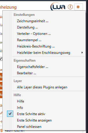
| Entry | Effect |
|---|---|
| Settings › Drawing units … | In which unit new parts are created and fields show dimensions – for all plug-ins, see Drawing units. |
| Settings › Display ... | Layer, color, linetype and lineweight per object type, hatch of the leader corridor, loop separated red/blue – see Display. |
| Settings › Manifold options … | Systems of supply and return, look of cabinet and rows – see Manifold options. |
| Settings › Room tag … | What the room tag of new rooms shows, shape – see Room tag. |
| Settings › Loop annotation … | What the loop text shows, coloring – see Loop annotation. |
| Settings › Heated areas at leader corridors › Ask · Always adapt · Always keep | What happens to heated areas a new leader corridor touches (default Ask). Also resets "Remember answer". |
| Properties › Property fields … | Which fields exist (default fields, own fields) – for all plug-ins. |
| Properties › Author … | The name in output – for all plug-ins, empty by default. |
| Layer › Create all layers of this plug-in | Creates missing layers of the plug-in; existing ones stay as they are. |
| Help › Help | This online help in the browser. |
| Help › Info | Version and program parts. |
| Help › Getting started active | Page cards and insertion help for this plug-in on or off. |
| Help › Show getting started | The tip wizard guides you through the page shown. |
| Help › Close palette | Close the palette – reopen it from the ribbon. |
The LuaCAD settings (for all plug-ins) are in the ribbon › tab LuaCAD › Info – see Getting started.
Dialog boxes
Room
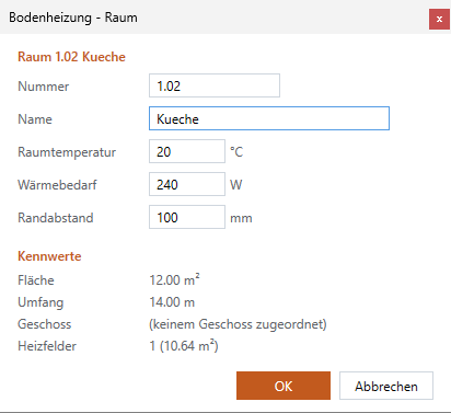
Rooms page › Change room ... or tools › Properties on a room. At the top "Room 1.01 Living", below it the values of the room; under Key figures for information area, perimeter, level and the heated areas with their area (and the number of divisions). Every field: Room.
Place loop
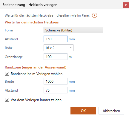
Comes before Place loop ... (with the check box "Always show before placing"). The same values as in the palette; OK stores them for all next loops and puts the loop at the cursor. Esc at the cursor returns here, Cancel ends. Every field: Place loop.
Loop
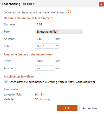
Change loop ... or tools › Properties on a heated area, loop or its leader. The values apply only to this loop; OK re-places it. Every field: Loop.
Room tag
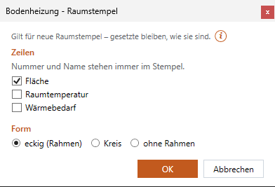
Gear menu › Room tag … or "..." next to the check box on the Rooms page. Applies to new room tags; stored in the annotation template "Room (Floor Heating)" – same as default = no own version. Every field: Room tag.
Loop annotation
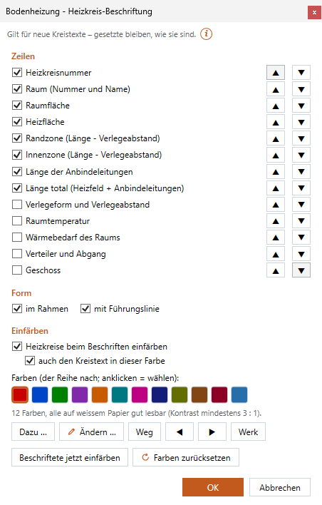
Gear menu › Loop annotation … or Output page › Loop text and coloring …. Applies to new loop texts; stored in the annotation template "Loop (Floor Heating)". If someone has written the template differently in the template editor, a note at the top says so – OK then replaces its text with the lines. Every field: Loop annotation.
Display
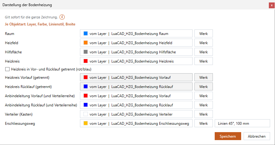
Gear menu › Display .... One button per object type: the attribute dialog box with layer (from the drawing), color, linetype and lineweight; Default resets the type. With Save the display applies to new objects and is transferred to all objects of this type in the drawing (one undo step). A loop colored when annotating keeps its color. Every setting: Display.
Manifold
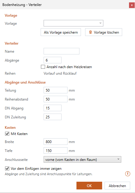
Comes before inserting (with the check box "Show the manifold dialog box before inserting") and with Change manifold … (title "Change manifold"). The values apply to the next or to the clicked manifold. The systems are fixed: supply and return. Every field: Manifold dialog box.
Manifold options
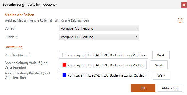
Gear menu › Manifold options …. Applies to all drawings. Every setting: Manifold options.
List options
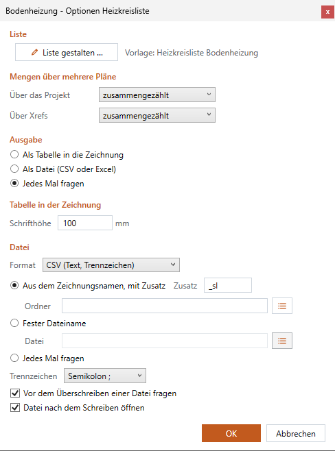
"..." next to Loop schedule or Bill of materials; the title names the list. Every setting: List options.
Property fields before inserting
With the check box Show properties before inserting (Manifold page) or from the section Property fields of the next loop (Loops page): the values go to every part you insert now; an ID is counted up. Esc at the cursor returns here. Change parts already inserted in the Properties palette.
Distance
A when inserting a manifold: the X and Y distances to the reference point and the base point in the 3 × 3 field. See Inserting at a distance.
Drawing units
Gear menu › Drawing units …: in which unit new parts come into the drawing and fields show dimensions (automatic, mm, cm, dm, m). Applies to all plug-ins – see Drawing units.
Questions
| Question | When | Choice |
|---|---|---|
| Adapt heated areas | A new or extended leader corridor touches heated areas. | Adapt heated areas · Keep heated areas; "Remember answer" (reset in the gear menu) |
| Leader corridor changed | Loops are connected automatically through the changed corridor. | Re-route · Keep (by hand) |
| Delete leader corridor | Delete segment at the trunk of a corridor with branches. | Whole corridor · This segment only |
| Manifold has too few outlets | Connecting all loops, but outlets are missing. | Extend outlets to n · Without these loops |
| Loop is already connected | Leader by hand on a connected loop. | Redraw by hand · Recalculate as bundle |
Every setting in detail
Here is every setting of Floor Heating – in the palette, in the gear menu and in the dialog boxes – with its effect, the default value and an example. Palette values apply only to parts you insert from then on and are saved immediately. Type dimensions in the unit of the field; every number field calculates ("600+400" becomes 1000). A "-" in the column "Default" means: the value depends on the data.
Palette, Rooms page
| Setting | What it does | Default | Example |
|---|---|---|---|
| Number | Room number of the next room; applies only to it, empty again afterwards. Empty = no number. | empty | 1.01 |
| Name | Room name of the next rooms. | Room | Living |
| Room temp. | Room temperature in °C (0 to 40) – value for tag, loop text and list. | 20 °C | 24 °C (bathroom) |
| Heat loss | Heat loss in W, optional – value for tag, loop text and list. | empty | 850 W |
| Insert room tag right away | Every new room gets its tag from the template "Room (Floor Heating)". | on | off when tracing many rooms |
Palette, Heated areas page
| Setting | What it does | Default | Example |
|---|---|---|---|
| Edge distance | Distance of the heated areas from wall and exclusion areas (0 to 2000 mm), for new rooms; per room under "Change room". Also the width of the joint at a division. | 100 mm | 150 mm |
Palette, Loops page
| Setting | What it does | Default | Example |
|---|---|---|---|
| Pattern | Counterflow (bifilar) or serpentine (single). | Counterflow (bifilar) | serpentine in the bathroom |
| Spacing | On-center spacing of the pipes, 30 to 1000 mm; ▾ = 50 to 300 mm. | 150 mm | 100 mm |
| Pipe | Outside diameter x wall thickness in mm; from it R min = 5 × d. | 16 x 2 (R min 80 mm) | 17 x 2 |
| Maximum loop length | Longest length of a loop in the area, 20 to 200 m. | 100 m | 120 m |
| Choose perimeter zone when placing | After the connector point click the walls of the perimeter zone. | off | on for rooms with exterior walls |
| Perimeter zone › Width | How far the perimeter zone reaches from the wall into the area, 100 to 5000 mm. | 1000 mm | 800 mm |
| Perimeter zone › Spacing | On-center spacing in the perimeter zone, 30 mm up to the on-center spacing. | half the spacing (75 mm) | 50 mm |
| Property fields of the next loop | Values for every newly placed loop (only those it does not yet carry). | no values | system "RFH-2F" |
| Always show before placing | The dialog box with the values before "Place loop". | on | off for fast work |
Palette, Manifold page
| Setting | What it does | Default | Example |
|---|---|---|---|
| Template | A manifold template brings all values, including the name. | (no template) | "Apartment manifold" |
| Outlets | Number of outlets, 1 to 24 (grayed out with "to match the loops"). | 4 | 8 |
| to match the loops | As many outlets as loops are attached – updated after every assignment. | on | off for a fixed manifold with spare outlets |
| With cabinet | Cabinet as an outline. | on | off |
| Show the manifold dialog box before inserting | The manifold dialog box first. | on | off |
| Show properties before inserting | The property fields of the manifold first. | off | on |
Palette, Leaders page
| Setting | What it does | Default | Example |
|---|---|---|---|
| Center-to-center distance | Distance supply/return, center to center, 20 to 300 mm – for the next drawing and connecting; remembered at the manifold. | 50 mm | 60 mm |
| Width (leader corridor) | Width of the next corridor, 100 to 5000 mm; during a run with Enter or the check mark. | 1000 mm | 1200 mm |
| Edge | Center · flush left · flush right – what the clicked line is. | Center | flush left along a wall |
| Spread across the width | The pipes in the corridor spread over the whole width instead of close to the edge. | off | on in a wide hallway |
| Spacing increment (while drawing, key A) | Rounding of segment lengths, 10 to 1000 mm; remembered. | 100 mm | 50 mm |
| Leaders in the insulation layer | May run under heated areas – per drawing. | off | on when the pipes lie below the screed |
Palette, Output page, and list options
| Setting | What it does | Default | Example |
|---|---|---|---|
| Evaluate visible objects only | Objects on layers turned off or frozen are left out of every list. | off | on |
| List options › Design list … | Columns, sorting, totals, filters, Excel template in the list layout dialog box. | default template | own template "Loops office" |
| List options › Quantities across the project / across xrefs | Together, per drawing or per level. | - | per level |
| List options › Output | As a table in the drawing · As a file (CSV or Excel) · Ask each time. | Ask each time | As a file |
| List options › Text height | Text height of the table in drawing units. | 100 mm | 150 mm |
| List options › Format | CSV (text, separator) or Excel workbook (.xlsx). | CSV | Excel |
| List options › File name | From the drawing name with suffix (and folder; empty = next to the drawing) · Fixed file name · Ask each time. | from the drawing name, no suffix | suffix "_loops" |
| List options › Separator | Separator of the CSV file. | semicolon | tab |
| List options › Ask before overwriting a file | Question if the file already exists. | on | off |
| List options › Open file after writing | Open the file afterwards. | on | off |
Room dialog box
| Field | What it does | Example |
|---|---|---|
| Number | Room number; empty = none. | 1.02 |
| Name | Room name. | Bathroom |
| Room temperature | 0 to 40 °C – value for tag, loop text and list. | 24 |
| Heat loss | In W, empty = no value; not negative. | 620 |
| Edge distance | 0 to 2000 mm; if it changes and the room has areas, they are rebuilt. | 120 |
| Key figures | For information: area, perimeter, height (if known), level (from the project, otherwise "not assigned to a level"), heated areas with area, divisions. | – |
Place loop dialog box
| Field | What it does | Default |
|---|---|---|
| Pattern, spacing, pipe, maximum loop length | As in the palette, Loops page. | counterflow, 150 mm, 16 x 2, 100 m |
| Choose perimeter zone when placing | Afterwards click the walls of the perimeter zone; without the check box width and spacing are grayed out. | off |
| Width, spacing | Width (100 to 5000 mm) and on-center spacing of the perimeter zone (30 mm up to the on-center spacing). | 1000 mm, half the spacing |
| Always show before placing | Without the check box the dialog box no longer comes – switch it back on in the palette. | on |
Loop dialog box
| Field | What it does | Example |
|---|---|---|
| Number | Loop number – at a manifold "manifold.outlet" (1.03), without a manifold numbered through. It applies to the first loop of the area. | 1.05 |
| Pattern | Counterflow or serpentine – the loop is re-placed in the new pattern. | serpentine |
| Spacing | On-center spacing, 30 to 1000 mm. | 100 |
| Pipe | Outside diameter x wall thickness, for example 16 x 2. | 17 x 2 |
| Perimeter zone › Width, spacing | Width (above 0) and spacing (30 mm up to the on-center spacing) of the perimeter zone of this loop. Which walls: "Choose perimeter zone". | 800 / 75 |
| Connector point automatic | Releases a connector point chosen by hand – only available if one is chosen. | – |
| Key figures | For information: length in the area (number of loops in the area), manifold and outlet. | – |
| chosen by hand (stays with Assign loops) | Only with an assignment by hand: without the check box "Assign loops" may move the loop to another outlet. | – |
Room tag dialog box
| Setting | What it does | Default |
|---|---|---|
| Lines › Area | The room area in m² below number and name. | on |
| Lines › Room temperature | The room temperature in °C. | off |
| Lines › Heat loss | The entered heat loss in W; without a value the line is dropped. | off |
| Shape | rectangular (frame) · circle · no frame. In a circle only number/name and the first selected line. | rectangular (frame) |
Loop annotation dialog box
| Setting | What it does | Default |
|---|---|---|
| Lines | Loop number · room (number and name) · room area · heated area · perimeter zone (length – spacing) · inner zone (length – spacing) · length of the leaders · total length (heated area + leaders) – on; pattern and spacing · room temperature · heat loss of the room · manifold and outlet · level – off. Arrows = order. | the first eight on |
| Shape › framed | Frame around the text. | on |
| Shape › with leader line | Leader line to the loop; without it only the text stands (it stays linked). | on |
| Color loops when annotating | Every annotated loop gets its own color (supply/return and both leaders); at a manifold the color of its outlet, neighbors never the same. | on |
| Loop text in this color too | Loop text, leader and frame in the color of the loop. | on |
| Colors | The palette in order (at least two); Add …, Change …, Remove, ◀ ▶, Default. | twelve colors, all readable on white paper (contrast at least 3 : 1) |
| Color annotated loops now | Color all loops of the drawing already annotated now (the settings are saved). | – |
| Reset colors | All loops back to the display of their object type, loop texts as their annotation style. | – |
Gear menu › Display
| Object type | Default layer (after LuaCAD_HZG_) | Default color (by layer) |
|---|---|---|
| Room | Floor heating room | 150 (blue) |
| Heated area | Floor heating field | 30 (orange) |
| Exclusion area | Floor heating helper area | 8 (gray) |
| Loop | Floor heating circuit | 1 (red) |
| Loop supply (separated) | Floor heating flow | 1 (red) |
| Loop return (separated) | Floor heating return | 5 (blue) |
| Supply leader (and manifold row) | Floor heating flow | 1 (red) |
| Return leader (and manifold row) | Floor heating return | 5 (blue) |
| Manifold (cabinet) | Floor heating manifold | 7 (black/white) |
| Leader corridor | Floor heating supply zone | 40 |
| Setting | What it does | Default |
|---|---|---|
| Button per type | Layer (from the drawing), color, linetype, lineweight; linetype and lineweight by layer by default. | default layer, everything by layer |
| Default | This type back to default. | – |
| Loop separated into supply and return (red/blue) | Off: the whole loop in the display "Loop". On: supply and return each in their own; the rows "(separated)" become available. The leaders always stay supply/return. | off |
| Hatch (leader corridor) | Lines (spacing and angle), solid fill or a pattern, with color; without an own color the color of the display. | lines at 45° with 100 mm spacing |
The layer is found through its key: you may change names, colors and linetypes in the GstarCAD Layer Manager – the assignment stays. The layer names shown are the English ones; they appear in the language of the program.
Manifold dialog box
| Field | What it does | Default | Example |
|---|---|---|---|
| Template, Save as template, Delete template | Choose a template (its values fill the fields); for a new one type a name and save – the same name replaces; applies to all drawings. | – | "Manifold 8" |
| Name | For list and annotation; empty = the next free one (V1, V2 …). | empty | M-2F |
| Outlets | Number of outlets (loops), 1 to 24. | 4 | 8 |
| Number to match the loops | As many outlets as loops are attached; without the check box the number applies. | on | – |
| Rows | Supply and return – fixed, for information only. | – | – |
| Outlet spacing | Distance between two outlets along the manifold, at least 20 mm. | 50 mm | 55 mm |
| Row spacing | Distance between the two rows across the manifold, at least 20 mm. | 50 mm | 60 mm |
| Outlet DN, supply inlet DN | Nominal size of the outlets or the supply inlet (number, empty = none). | 15, 25 | 20, 32 |
| With cabinet | Cabinet as an outline. | on | – |
| Width | Width of the cabinet; empty or 0 = from the number of outlets (the tooltip gives it). Too narrow = message. | empty | 800 mm |
| Depth | Depth of the cabinet. | 150 mm | 110 mm |
| Outlet side | front (from the cabinet into the room) · back (through the back wall) – the arrow in the cabinet shows it. | front | back for pipes from the next room |
| Always show before inserting | Without the check box the manifold hangs at the cursor right away next time (switch back on in the palette). | on | – |
Gear menu › Manifold options
| Setting | What it does | Default |
|---|---|---|
| Systems of the rows › Supply | System of the supply row (list of the Piping systems). | Default: the system of the heating supply |
| Systems of the rows › Return | System of the return row. | Default: the system of the heating return |
| Display › Manifold (cabinet) | Layer, color, linetype, lineweight of the cabinet; Default = back. | default manifold layer, by layer |
| Display › Supply / return leader (and manifold row) | Look of the leaders and of the rows of the manifold. | default supply / return layer, by layer |
Further settings
| Entry | What it controls | Default |
|---|---|---|
| Gear menu › Heated areas at leader corridors | Ask · Always adapt · Always keep. | Ask |
| Gear menu › Drawing units … | Unit of new parts and of the fields – for all plug-ins. | - |
| Gear menu › Property fields … | Which fields exist – for all plug-ins. | – |
| Gear menu › Author … | The name in output – for all plug-ins. | empty |
| Gear menu › Help › Getting started active | Page cards and insertion help for this plug-in. | on |
Typical notes and errors
| Message | What it means | What to do |
|---|---|---|
| There is no room of Floor Heating – please click into a room or on its edge. | The click hit no room. | Click into the room. |
| There is no closed polyline … | Room from polyline: open polyline or nothing. | Close the polyline or pick points. |
| A room needs at least three corners. · The outline is not a valid polygon … | Too few or duplicate points. | Pick again. |
| Note: the new room overlaps room … | Two rooms overlap. | Check the outlines. |
| Room …: no heated area possible (too narrow for the edge distance). | Room too narrow. | Smaller edge distance (Change room). |
| There is no heated area – first "Generate heated areas". | Place loop without an area. | Generate heated areas. |
| The line does not divide any heated area … | Dividing line does not cross an area completely. | Draw from wall to wall. |
| These areas are not separated by a division … | Join without a division between them. | Click only areas at a division. |
| The area is too narrow for supply and return with the minimum bend radius … | No loop fits. | Smaller spacing or smaller pipe. |
| The area is separated at a narrow point – it is divided into n partial areas … | Note. | Check the result. |
| A hole in the area could not be bypassed … | Exclusion area in the middle of the area. | Divide the area at the exclusion area. |
| The counterflow pattern is connected at a corner … | Connector point in the middle of a wall. | Accept or choose serpentine. |
| A loop would be longer than the maximum loop length … – the area is divided into n … loops. | Maximum loop length reached. | Intended; otherwise adjust the maximum loop length. |
| Warning: the loop is … long – more than the maximum loop length … · Loop … with leaders … – longer than the maximum loop length … | Too long with the leaders. | Manifold closer, divide the area. |
| This only works with a loop … – first "Place loop". | Area without a loop clicked. | Place a loop first. |
| There is no wall of this room – please click closer to the wall. | Choose perimeter zone. | Closer to the wall. |
| Serpentine: a perimeter zone across the rows cannot be laid closer … | Serpentine and perimeter zone across. | Choose counterflow. |
| The spacing must be between 30 and 1000 mm. · Please enter the pipe as outside diameter x wall thickness … · The perimeter zone needs a width above 0 … · Please enter a valid maximum loop length … | Input error in the dialog box. | Correct the value. |
| The room temperature must be between 0 and 40 °C. · The edge distance must be between 0 and 2000 mm. · The heat loss must not be negative. | Input error in the Room dialog box. | Correct the value. |
| The center-to-center distance must be between … – the previous value applies. · The width of the leader corridor must be between … | Palette value outside the allowed range. | Type a value within the range. |
| There is no manifold yet – first "Insert manifold". | Connecting without a manifold. | Insert a manifold. |
| No loop is attached to this manifold yet – first "Assign loops". | Empty manifold. | Assign. |
| n loop(s) without a free outlet … | Manifold too small. | More outlets or "to match the loops". |
| Manifold … already has the highest number of 24 outlets … | Limit reached. | Insert a second manifold. |
| No route found for n loop(s): … – the leader ends before the loop or is missing … | No route around the heated areas. | Continue by hand with "Single", a leader corridor or the insulation layer. |
| Caution: n crossing(s) in the bundle … – "All loops" reorders the outlets. | Individual loop crosses others. | "All loops of a manifold". |
| n loop(s) without an orthogonal route – drawn straight, please check. | Fallback. | Draw by hand. |
| Not drawn from the outlet to the loop – nothing changed. | Run by hand not started at the outlet. | Start at the outlet. |
| Loop …: the leader is drawn by hand – cross and swap only work on automatic … | Cross on a leader by hand. | Automatic again, then cross. |
| There is no room in front of the cabinet for the crossing – they change sides inside the cabinet. | Note. | – |
| There is no straight segment of a leader. · It does not go that far … | Move. | Another segment, less far. |
| …: the supply/return cannot be followed unambiguously … | Grip on a leader, partner unclear. | Redraw the partner yourself or stretch both together. |
| …: supply and return now come too close or cross … | After a grip. | Redraw. |
| Loop … is now by hand … · Heated area … is now by hand … · Leader of loop … is now by hand … | Note after a grip. | "Automatic again" if needed. |
| The surface of a leader corridor follows its centerline … | Corridor surface deformed. | Change the centerline. |
| The two corridors do not meet with their ends … · The two corridors do not touch … | Join. | Place corridors end to end or as a tee. |
| A leader corridor needs at least two points – "Delete" removes it completely. | Remove vertex on the last segment. | Delete. |
| LuaCAD: layer "…" is locked – part not changed. | Part on a locked layer. | Unlock the layer and repeat. |
| n issue(s) – details in the log. | "Check" found something. | Read the lines above. |
| That did not work – see the log. | An unexpected error. | Repeat; otherwise send the log to support. |