
Connectors
The connector types
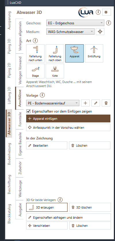
On the Connectors page all types are tiles. Below the tiles it says what the chosen type is for.
| Type | Purpose | Template |
|---|---|---|
| Stack down | The water leaves here – the start of a drainage network. | yes |
| Stack up | Brings water from above into the pipe (DU, Qww or pumped discharge line). | yes |
| Fixture | Lavatory, toilet, shower … with its discharge unit DU. | yes |
| Vent | A vent connector, without load. | yes |
| Offset | The pipe steps in elevation – downward in the flow direction (30/45/60/90°), the inlet lies higher. | – |
| Spot elevation | A fixed elevation on the pipe (top, centerline or invert). | – |
You also insert stacks, fixtures and vents with the four tiles on the General routing page – it is the same command. Offset and spot elevation always sit on a plumbing line and take level and system from it.
Inserting a stack
Goal: place the stack down – the start of the drainage network – or a stack up that brings water from the levels above.
- Choose the Stack down (or Stack up) tile and the template in the Template list.
- Click Insert stack down (the button is named after the type).
- Place the stack at its position in plan; close to the end of a line it snaps there.
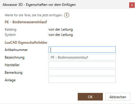
- With the check box "Show properties before inserting" the property fields appear before the cursor and the connector dialog box after placing.
- Enter = done, Esc = cancel. Then draw the plumbing lines up to the stack.
Keys at the cursor
| Key | Effect |
|---|---|
| Space | line snap off/on (with a distance: next base point) |
| L | line snap off/on while the Space key switches the base point |
| A | distance to a reference point |
| E | values of the next stack |
What the stack dialog box contains
- Stack pipe and outlet – the diameter of the stack (a minimum; "Generate 3D" never sizes smaller) and of the outlet ("auto" = from the sizing).
- Fixed size (independent of the calculation) – downward only: the stack pipe gets exactly the chosen diameter. If the calculation gives more, a note appears in the result. Without the check box, "Generate 3D" sizes the stack of a riser divided across levels with the load of the levels above – never smaller than chosen.
- Fittings – continuation above, main fitting (wye 88½°, curved wye, wye/elbow 45°, ball wye, double 45° bend, elbows, straight, fitting by hand …), continuation below; plus blockout, "Fully shortened", "Bottom of fitting instead of invert" and "Connect without branch offset".
- Elevation – top and invert: automatic, from TOS, from BOS, absolute or (invert) from the fittings; ==, >=, <=.
- Drainage network › Building drain – downward only and effective only under DIN: how the building drain of the network runs (inside, outside, outside behind a manhole with open flow).
- Load from above – upward only: calculation basis, sum of DU or individual fixtures, Qww, frequency factor, continuous flow, pumped discharge line, stack height (DIN).
Every field: Connector dialog box.
Inserting a fixture or vent
Goal: place the point where a fixture discharges into the network – on the end of a plumbing line or simply free; the line follows afterwards.
- Choose the Fixture (or Vent) tile and the template (toilet, lavatory, shower …).
- Click Insert fixture.
- Close to the end of a line the connector snaps there. Above a line it drops perpendicular onto it – the line is divided there. With no line nearby it stands free.
- Click; the next one hangs at the cursor. Enter = done, Esc = cancel.
The keys are the same as for the stack.
What the fixture dialog box contains
- Template, short name (appears in annotations and lists), level, system, manufacturer, product line, diameter (a minimum; some fittings only exist in fixed diameters – then the list shows only these).
- Fittings – continuation above, main fitting (pipe, push-fit coupling, roof drain, floor drain, floor inlet, shower tray waste, elbows …), blockout, "Connect without branch offset".
- Elevation – top and invert as for the stack; for a floor drain the top is called installation elevation.
- Connector – DU in l/s (at least 0.05), Vented (sizing with the table for vented pipes), Custom part (a DWG instead of the main fitting), Axial offset.
- Floor drain / floor inlet – Offset (none, 45°, 90°), Electrofusion coupling (none, at the outlet, at the offset), Supplied (which supplied floor drain is inserted: the generic standard or the version with a product name – only without a custom part).
- Vent – Relief vent (downward connector) and axial offset.
Offset
Goal: let the pipe step in elevation at one place – downward in the flow direction, the inlet lies higher.
- Choose the Offset tile. Below it, the angle of new offsets: 30°, 45° (default), 60° or 90°.
- Click Insert offset and click the place on a plumbing line – the point runs along the line.
- In the dialog box set the angle, the position (before the connector, exactly at the connector, after the connector) and the offset (with "automatic", "Generate 3D" calculates it from the elevations).
"Generate 3D" places two elbows at the chosen angle there. If a fixed inlet lies higher and no offset is set, "Generate 3D" inserts a 45° offset itself and says so in the result – an offset of your own takes precedence.
Spot elevation
Goal: fix the elevation of the pipe at one place, for example at a wall penetration.
- Choose the Spot elevation tile, click Insert spot elevation and click the place on a plumbing line.
- In the dialog box under Spot elevation here: absolute, from TOS or from BOS, plus ==, >= or <= and the value; the crosshair picks an elevation.
- Relative to: top, centerline or invert of the pipe.
"Generate 3D" builds the slope so that the pipe has exactly (==), at least (>=) or at most (<=) this elevation there. Without a spot elevation the elevation results from the slope from the stack.
Templates
Goal: define the values of a connector once and reuse them for every new one – for example "toilet" or "shower".
- Choose the type (stack down/up, fixture, vent); the Template list shows its templates.
- + creates a new one (a copy of the selected one), the pencil edits the selected one, the recycle bin deletes it.
- The dialog box is the same as the connector dialog box, with the name of the template at the top (unique per type). Level and system come from the palette when inserting.
Every newly inserted connector gets the values of the chosen template. Connectors already inserted stay as they are – you change them with Edit. The tooltip of the list shows product line, diameter, DU, main fitting and whether vented.
Base point and distance before inserting
Goal: place a connector at a fixed distance from a point without searching for the position at the cursor first.
- Click Base point: choose in the preview. The preview shows the connector from above, with the base points around it.
- Choose the base point and the distance.
- When inserting, the connector then hangs at the cursor once, with this base point and distance – click the reference point (for example a wall corner).
At the cursor A does the same; the Space then switches the base point, the distance stays. See also Inserting with a distance.
Stack across levels
Goal: distribute a stack that reaches across several levels onto the drawings of the levels right away.
- Choose the Stack down or Stack up tile. Stack across levels appears only in a project drawing with levels.
- Under To choose the level up to which it reaches – downward the levels below, upward the levels above (default "this level only").
- Insert the stack. LuaCAD asks whether it is divided across the levels right away: every level up to there gets the matching stack in its drawing (passing through or at the end).
Afterwards: gear menu › Levels › "Divide across levels …". If the stack is moved later, LuaCAD asks which levels follow; stack symbol and the plumbing lines on it go along. The target drawings must be closed and writable for this. How dividing across levels works in general: Divide across levels.
Editing and deleting connectors
- Edit (In the drawing): click connectors or drag a selection window and change them in the connector dialog box.
- Delete (In the drawing): click connectors or drag a selection window and delete them.
- If the network already has 3D, lines and connectors are hidden – after "Delete 3D" they are back. After a change LuaCAD asks whether the 3D is generated again.
Fixtures from the Block Library
Fixtures from the Block Library … (General routing and In-wall carrier routing pages) opens the Block Library on the Fixtures page: lavatory, toilet, shower … as a block with 2D, 3D and connectors. The drainage connector comes along and lies on the layer of the connectors (not plotted). The Fixture tile, on the other hand, inserts only the connector – it is enough for the calculation.