
Piping 2D
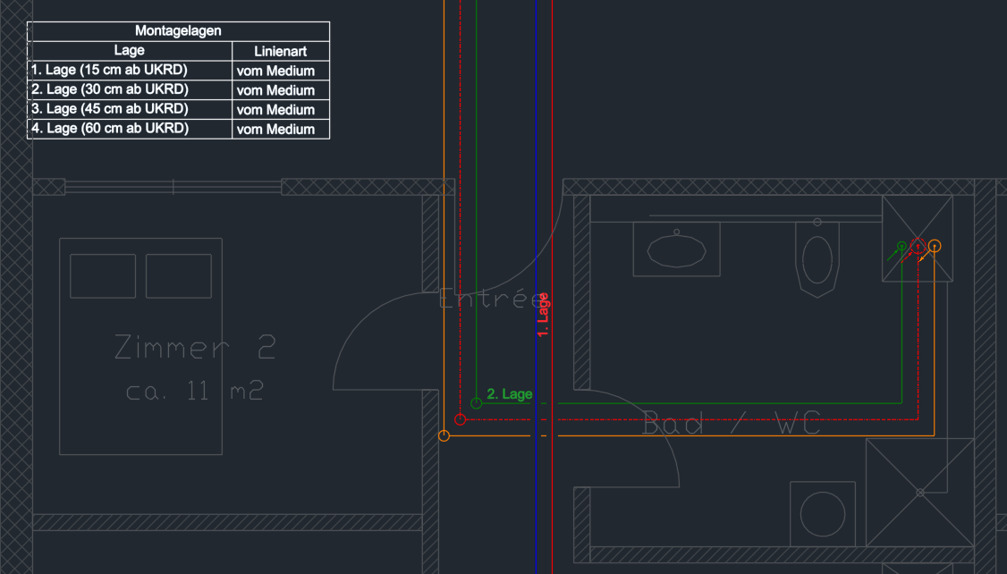
With Piping 2D you draw piping plans in plan view as single-line pipes: every pipe is an ordinary line (or polyline) of the CAD with a system and a system elevation – no elevation value, no level, no catalog. On top come risers (vertical pipes shown as a rise/drop symbol), connectors of fixtures, valve symbols in the pipe, manifolds with flexible PEX pipes, the marking of system elevations and the bill of materials. Where a pipe crosses a higher system elevation, Piping 2D breaks it there by itself; where a pipe changes its system elevation, a circle shows the change.
A plan from Piping 2D can later be converted to 3D in Piping 3D – see Converting 2D to 3D.
How this help is organized
From overview to detail – read only as far as you need right now:
| Part | What you will find | For whom |
|---|---|---|
| Quick start | Insert and edit a simple pipe in a few steps – one picture per step. | Anyone drawing their first pipe today |
| Concepts | Rigid and flexible pipes, system elevation, crossing and elevation change, system, size, riser, connector, symbol, manifold. | Anyone who wants to understand how Piping 2D works |
| Tasks | Every function of the palette and of the action bar in detail: goal, steps, keys, options, example, notes – with a short video at the end. | Anyone who needs a particular function |
| Reference | All buttons per palette page, all keys, the gear menu, the dialog boxes, every setting in detail and the typical messages. | Anyone looking for something specific |
The tasks are ordered by work step: Drawing pipes, Risers and connectors, Symbols, Manifolds and PEX pipes, System elevations and crossings, Editing pipes and Output.
Overview
A piping plan is created step by step:
- In the gear menu › System elevations create the system elevations of the drawing (for example "in the floor" and "below the ceiling") – they are the same system elevations as in Piping 3D. How each one is drawn is set in the gear menu › Elevation marking.
- On the Pipe page choose system and system elevation, and if you like the size and "flexible".
- Click Insert pipe and click the pipe point by point – or several side by side with Insert parallel pipes.
- Add risers, connectors, symbols and manifolds – see Inserting risers, Inserting connectors, Inserting a symbol and Inserting a manifold.
- Change things with the tools below every page, with grips or with the GstarCAD commands – see Editing pipes.
- Output elevation symbols, the elevation table, the bill of materials and annotation – see System elevations and crossings and Output.
| Page | What you will find |
|---|---|
| Drawing pipes | Inserting a pipe, distance before the first point, system elevation, wall offset and fixed length while drawing, parallel pipes, picking pipes, flexible, connecting, property fields of the next pipe |
| Risers and connectors | Choosing a template, inserting risers, inserting connectors, managing templates, editing risers and connectors, axis cross, fixtures from the Block Library |
| Symbols | Inserting, moving and deleting a symbol, custom symbols with the symbol wizard, symbol folder |
| Manifolds and PEX pipes | Values of the next manifold, inserting, changing, flipping the outlet side, deleting, connecting a manifold, connecting connectors, manifold options |
| System elevations and crossings | Creating system elevations, crossings, elevation changes, elevation marking, elevation symbols, elevation table |
| Editing pipes | Selecting, properties, changing the system elevation, Move, Break, joining, Delete, grips and CAD commands, Check |
| Output | Bill of materials, lists across several plans, updating lists, annotation, converting to 3D |
The pages of the palette
Open the palette on the ribbon › LuaCAD tab › Piping 2D; how a palette is laid out is explained in Getting started. Each page has an "i" at the top with a short explanation; "More in the online help" leads to the sections here. Every button of a page is listed in the Reference, every setting under Every setting in detail.
Below every page are the same tools (Connect, Move, Break, Delete, Properties, Change system elevation, Check). What you change in the palette applies right away – also while you are drawing a pipe.
Pipe
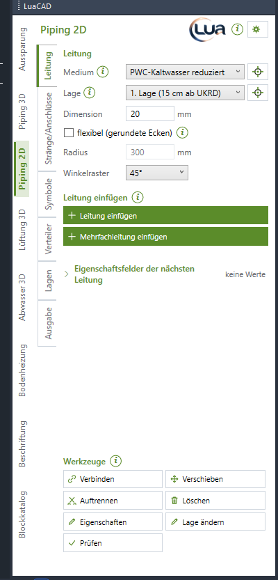
Here you set what the next pipe is inserted with: system (color, layer), system elevation (linetype, which pipe lies on top at a crossing), optionally the size in mm, whether it is flexible with rounded corners, and the angle increment it follows. Then click Insert pipe and click point by point, or Insert parallel pipes for several pipes side by side from the riser template chosen last.
Tasks on this page: Inserting a pipe · System elevation, wall offset and fixed length while drawing · Parallel pipes · Flexible · Property fields of the next pipe · All settings of this page
Risers/connectors
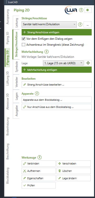
A riser is the sign of a vertical pipe in plan view: a circle with an arrow up, down or through. Connectors are the pipe ends of a fixture. In the list you choose a riser template or a connector template, "…" manages them, Insert riser/connectors inserts what is selected in the list. Parallel pipes start at the risers of the riser template chosen last.
Tasks on this page: Choosing a template · Inserting risers · Inserting connectors · Managing templates · Editing risers and connectors · Axis cross · Fixtures from the Block Library
Symbols
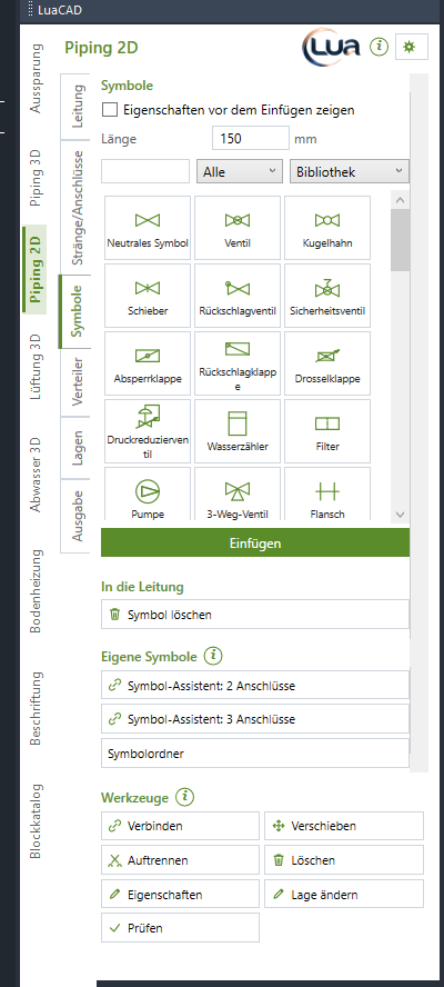
A symbol (ball valve, valve, pump …) sits in a gap of the pipe: it cuts the pipe open by its length and places its line drawing in it, in the color and on the layer of the system. Click a symbol in the list, click Insert (or double-click), then the pipe. Custom symbols are made with the symbol wizard from a drawn DWG.
Tasks on this page: Inserting a symbol · Moving a symbol · Deleting a symbol · Custom symbols · Symbol folder
Manifold
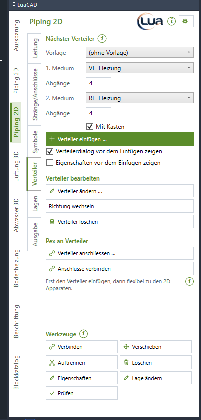
At the top are the values of the next manifold: one system or two mixed (for example cold and hot water), separate outlets per system, with or without a cabinet; a template brings all values including the name. Each outlet and the supply inlet act as connectors. Below you connect the manifold with flexible PEX pipes to the connectors of the 2D fixtures.
Tasks on this page: Next manifold · Inserting a manifold · Changing, flipping, deleting · Connecting a manifold · Connecting connectors · Manifold options
System elevations
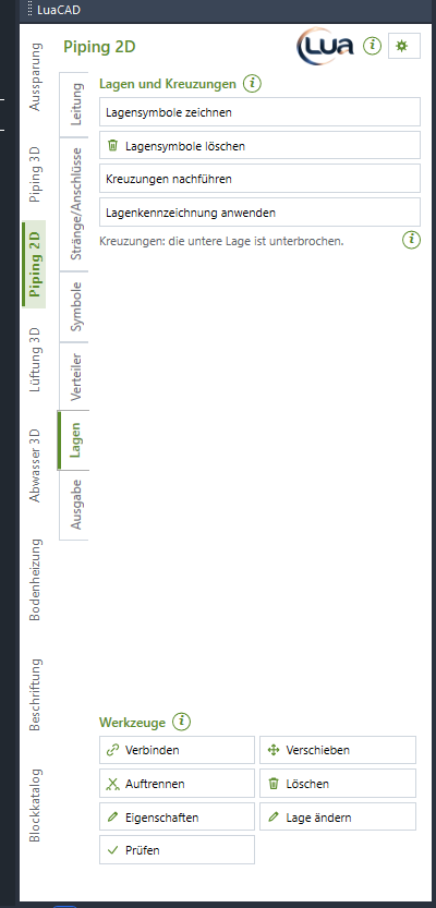
Every pipe lies on a system elevation, for example in the floor or below the ceiling. Every system elevation has an abbreviation and its own linetype. Elevation symbols write the abbreviation or slashes next to the pipe, the elevation table (Output page) explains them. Where a pipe crosses a higher system elevation, it is broken there by itself. You create the system elevations in the gear menu › System elevations, their look in the gear menu › Elevation marking.
Tasks on this page: Creating system elevations · Crossings · Elevation change · Elevation marking · Elevation symbols · Applying elevation marking
Output
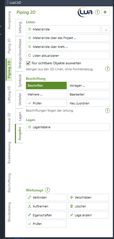
The bill of materials (pipe lengths per size and counted fittings) as a table in the drawing or as a file, also across several plans; annotations from templates that stay attached to the pipe and follow it; the elevation table. Piping 2D has no pipe list – only the bill of materials. An IFC file is available only after converting to Piping 3D.
Tasks on this page: Bill of materials · List options · Across several plans · Updating lists · Annotating · Elevation table
Tools (below every page)
You see the tools at the bottom of every picture of a palette page: two columns of small buttons – Connect and Move, Break and Delete, Properties and Change system elevation, then Check; the "i" next to the title explains them.
The tools are on every page and act on whole pipes; crossings and rounded corners follow by themselves. You select by clicking or with a selection window – also object first, then the button. Properties takes pipes, risers and free connectors together, Properties and Delete also a manifold you click.
Tools in this footer: Connect · Move · Break · Delete · Properties · Change system elevation · Check
Keys at the cursor
During a function the action bar at the cursor shows every key that currently applies – click it or press it. In all plug-ins the same key means the same thing; the full list is in the Reference.
| Key | Meaning |
|---|---|
| A | before the first point: distance to a reference point; while drawing: system elevation, wall offset and fixed length; Move: distance or wall offset |
| Space | while drawing: snap to angle / free; at a part: switch the base point; risers: next riser at the cursor |
| W | pick an angle (two clicks) |
| D | type an angle |
| R | rotate (riser row, connectors, manifold) |
| S | parallel pipes: risers to the other side; manifold: outlet side front/back |
| M | manifold: mirror (top/bottom, left/right) |
| P | match the properties of a pipe you click; parallel pipes before the first point: pick pipes |
| N | match the system only |
| ← / → | with a wall offset: switch the side of the pipe |
| Enter | finish |
| Esc | cancel – while drawing, the placed segments stay |
The Help button in the bar opens the help for the running function.