
Editing parts
The buttons for changing parts are on the Ducts, Round ducts, Flexible ducts, Duct accessories, Products and Custom parts pages below Insert. Every command is one undo step; the adjacent parts adapt in the same step.
Selecting several parts
Goal: select several parts for Move, Move elevation, Change properties or Delete.
- Click the first part (1). Each further click adds a part; clicking a selected one deselects it.
- Shift + click (2) selects all parts on the way from the last selected one to this one – a whole run in one go.
- Click beside the parts and drag a selection window (3): from left to right takes what lies completely inside, from right to left what it touches.
- Enter = finish, the command continues. Esc = cancel – the command does nothing.
Editing with grips
Goal: change a duct, a round duct or a fitting directly with the mouse, like a CAD object.
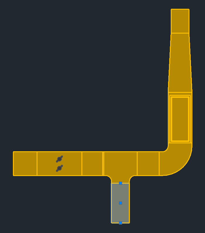
- Click a part – the grips appear.
- Click a grip, drag it and click at the new place.
- At the end of the command the adjacent parts adapt – with the same rules as Move.
| Grip | Effect |
|---|---|
| Start/end at an open end | The duct section becomes longer or shorter (down to the minimum length). An end cap at the end and what sits on it move along. |
| Middle of the duct section | The whole section moves – like "Move" on the palette. If it consists of several pieces, the grips still appear only once. |
| Elbow, tee, offset (at the node) | The node moves in the plane of its connectors; the attached sections follow. Example in the picture below. |
| In-line part (middle) | The part slides along its duct – see Moving an in-line part. |
The movement works in the view: in plan view and in oblique views only in X and Y, in a side or front view in the picture plane – so also in elevation.
Move
Goal: move ducts and parts in plan – the attached ducts become longer or shorter, an offset is created where needed. The elevation stays.
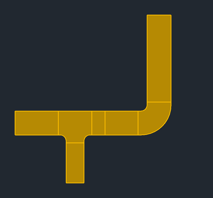
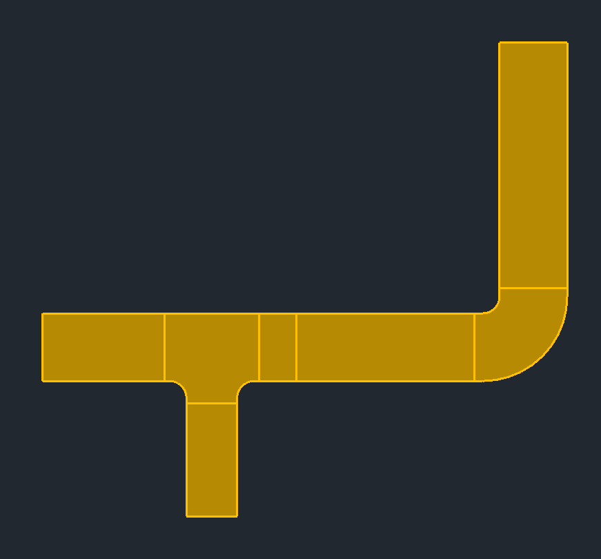
- Move. The first time, the insertion help appears with a picture.
- Select the parts – in the picture the duct section after the elbow (1) – click, Shift + click from–to or a selection window; Enter = selection finished. A straight piece takes its whole duct section along.
- Click the new position – or type a distance.
- Adjacent straight ducts in line become longer or shorter (2); if the neighbor lies across the movement, an offset fitting or a pair of offset elbows makes up the offset.
Keys at the cursor
| Key | Effect |
|---|---|
| L | only along the section |
| Q | only across the section |
| Space | free in all directions in plan |
| A | type a distance |
Moving an in-line part
Goal: slide a damper, a sound attenuator, a product or a custom part along the duct to another spot.
- Drag the grip in the middle of the part – or click Move and select only this part.
- The part slides on the axis; the ducts before and after become shorter or longer. Limits are the next fitting, an open end or a surface-mounted part – with the minimum length of the Parameters page in between.
- A click places it.
The same applies to the CAD command MOVE when only this part is selected: along the duct it slides, across it the whole line moves.
Move elevation
Goal: change only the elevation of selected parts – X and Y stay, the adjacent parts get an offset fitting or offset elbows.
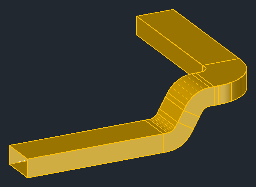
- Move elevation and select the parts; Enter.
- Give the new elevation:
- with the cursor – up or down in a side or front view; in plan view: up in the picture = higher;
- A = type the elevation (absolute or from level: TOS, BOS, FF, FC and value, with pick);
- P = pick the elevation in the drawing (a point with object snap).
- A click or OK places it. Up to the duct height an offset fitting is created, above that offset elbows – see Elevation change.
Query properties
Goal: see all values of a part and correct them.
- Query properties and click a part – it stays highlighted.
- In the dialog box (fitting properties or accessory properties) go through the General, Dimensions and Connectors tabs and change what is needed.
- OK rebuilds the part. If you change size, system or insulation and the part belongs to a larger network, LuaCAD asks: Only this part (with a new size, reducers are added at the ends) or Whole network (size: all straight pieces of this line; system and insulation: all parts of the network).
- Then click the next part right away; Enter = finish.
Every field of the dialog box: Reference › Properties.
Change properties
Goal: change system, insulation, size or elevation of many parts at once.
- Change properties and select the parts (Selecting several parts); Enter.
- In the dialog box enter only what should change. A field showing "different – stays" leaves each part its own value.
- A new size applies to the straight pieces and elbows; at the edges of the selection a reducer or transition to the neighboring size is added. With the new size, keep chooses which edge runs through: centerline, top edge or bottom edge (for round ducts crown or invert).
- Relative elevation raises (more than 0) or lowers (less than 0) the parts; adjacent straight ducts get an offset at the ends.
- OK.
Segment
Goal: divide a straight duct at one point – or re-segment a whole run into pieces of the maximum length.
- Segment and click a straight duct or round duct.
- Choose on the command line: Divide (default) or Re-segment.
- Divide: choose the dividing point on the duct – the cursor runs along the axis; the minimum length stays on both sides.
- Re-segment: the whole straight run is divided again by the maximum length of the Parameters page, starting from the end nearer the click.
- Esc chooses another part, Enter = finish.
Delete
Goal: delete parts – the adjacent parts get open connectors.
- Delete and select the parts (click, Shift + click, selection window); Enter.
- If the network has further parts, LuaCAD asks: Delete only the selected parts (the neighbors stay and get open connectors) or Delete the whole network. With "Remember answer" the choice applies from then on – reset it in the gear menu › Options › Edit.
Divide across levels
Goal: spread a riser duct or a round riser across a level boundary into the drawings of the levels – each piece goes into the drawing of its level.
- Divide across levels … (Ducts and Round ducts pages) and select the duct or a part on it (click or selection window, Enter = finish).
- In the dialog box choose up to which level.
- Each piece goes into the drawing of its level (this discipline); surface-mounted parts go with their piece.
If a duct run crosses the boundary while you draw, LuaCAD asks right after the run. In the other level the duct run starts at the end of the riser duct (level xref shown). If a divided duct is moved, LuaCAD asks which levels follow; the drawings there must be closed for this. Divide objects across levels … checks the whole drawing – all plug-ins – and shows what reaches beyond the dividing plane, to choose from. Check risers (gear menu › Levels) finds dividing points that no longer match.
Dividing needs a project with levels and the level function switched on (gear menu › Levels › Divide across levels settings …). The workflow is the same in all plug-ins – details under Piping 3D › Risers across several levels.
CAD commands on ventilation parts
Goal: edit ventilation parts with the familiar GstarCAD commands.
| Command | What LuaCAD does afterwards |
|---|---|
| MOVE, ROTATE, MIRROR | The adjacent parts are updated at the end of the command. An in-line part alone moves like with its grip. |
| COPY | The copy is a new part with its own ID; a copied part of a divided riser duct carries no level mark. |
| STRETCH, SCALE | A 3D solid jumps back – change the length with the grip or in the properties. |
| ERASE | The adjacent parts get open connectors, as with "Delete" on the palette. |
| Properties palette | Shows the values of the part under LuaCAD (system, size, property fields …). |
What happens to the rest of the network when you select with one of these commands – ask each time, only the selected part, or always the whole network – is set in the gear menu › Options › Edit. If a part lies on a locked layer, LuaCAD does not change it and says so.