
Floor heating concepts
This page explains the terms you need to understand the functions. Pictures sit side by side where the difference matters.
From room to loop
A floor heating system is built in stages – each stage is derived from the previous one:
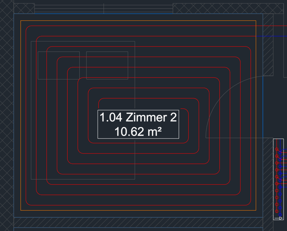
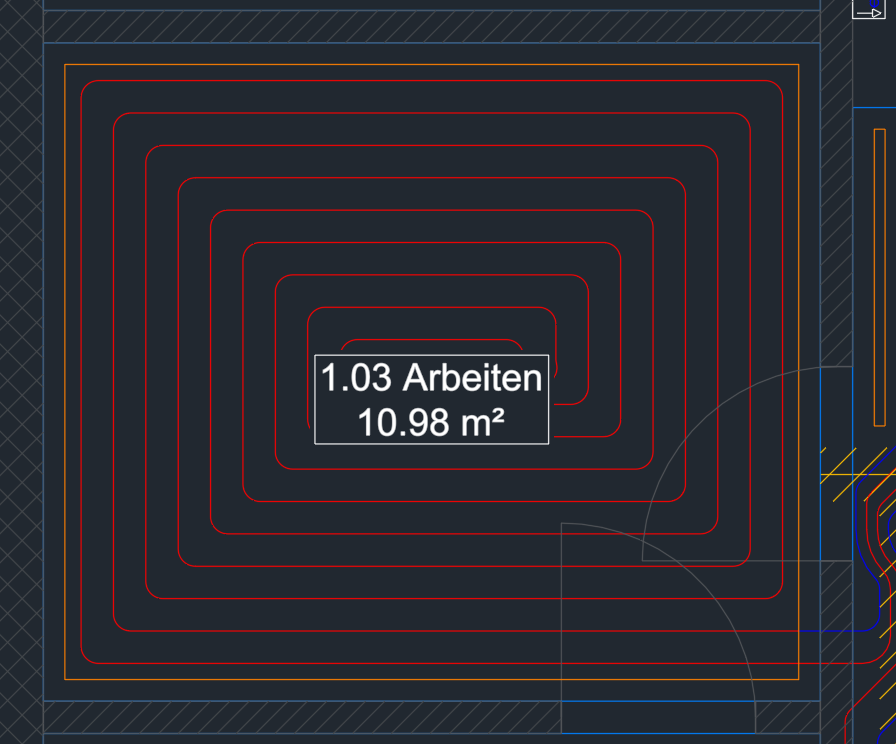
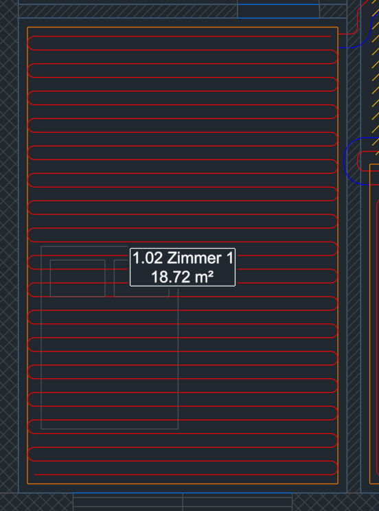
You draw only the room. The heated area and the loop are derived: when the room changes, both are rebuilt with their values. This holds until you adjust a loop or area yourself – then it is "by hand" (see Automatic and by hand).
Room
A room is a closed polyline with room data: number (may stay empty), name, room temperature, optionally the heat loss in W, and the edge distance of its heated areas. Room temperature and heat loss are values for room tag, loop text and list – nothing is calculated from them. The room also has its room tag (an annotation that follows it). The outline is the polyline itself: GstarCAD grips, MOVE, COPY and MIRROR act on it directly.
Exclusion area
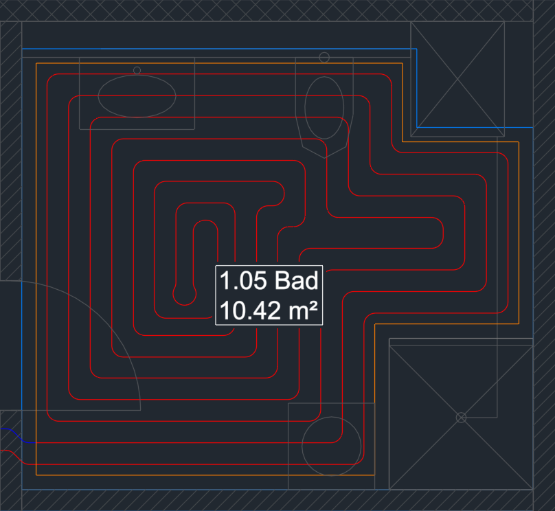
An exclusion area is a spot without floor heating: shaft, kitchen counter, built-in closet, shower. It belongs to the room it lies in; the heated area leaves it out with the edge distance. When the exclusion area changes, the areas of the room are rebuilt.
Heated area, edge distance and division
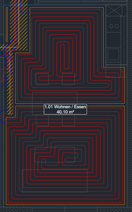
A heated area is the surface where the pipes lie: the room minus its exclusion areas, offset inward by the edge distance (100 mm by default). A niche narrower than twice the edge distance is dropped; a narrow passage separates two areas.
You divide a large room into several areas with a dividing line. The division belongs to the room and stays when the room changes; between the areas there is a joint as wide as the edge distance. Every area gets its own loops.
Loop, supply and return
A loop is a pipe from the manifold through the area and back: the supply brings the warm water, the return takes it back. In the drawing these are two polylines – by default in one color (red, layer of the loop); separated into red/blue with a check box under gear menu › Display.
Every loop has:
| Value | Meaning |
|---|---|
| Number | At a manifold "manifold.outlet", for example 1.03 = manifold 1, outlet 3; without a manifold numbered through the drawing. |
| Pattern | Counterflow or serpentine (see below). |
| On-center spacing | Distance between the pipes, center to center; 150 mm by default. |
| Pipe | Outside diameter x wall thickness, 16 x 2 by default. From it the minimum bend radius 5 × d (16 mm → 80 mm); every bend keeps it. |
| Connector point | Where supply and return leave the area – automatically on the side toward the manifold, or chosen by hand. |
| Perimeter zone | Walls along which the pipes lie closer together (see below). |
| Length | Length in the area plus the leaders to the manifold. |
Counterflow and serpentine pattern
| Counterflow (bifilar) | Serpentine (single) | |
|---|---|---|
| Path | Supply and return run side by side as a rectangular spiral inward and outward; the turn is in the middle. | The rows run back and forth, across the connector wall. |
| Heat | Every warm pipe has a cooler one next to it – the surface warms evenly. | Warmer at the start – good in front of windows and in bathrooms. |
| Connector | At a corner of the area. | Anywhere along the wall. |
| Bends | Every bend keeps the minimum bend radius; the change of ring is at a corner. | Where the rows are closer than the bend radius allows, the pipe makes a loop instead of a tight half circle. |
The counterflow pattern is the default. The pipes run around a column or a shaft – it stays one loop.
Perimeter zone
In front of an exterior wall or a window the pipes lie closer together – it gets warmer there. The perimeter zone has a width (how far it reaches into the area, 1 m by default) and its own spacing (by default half the on-center spacing). You choose the walls that belong to it per loop.
Maximum loop length
A loop may be at most this long – 100 m by default (allowed 20 to 200 m). If a loop in the area would be longer, the plug-in divides the area into loops of about equal length; if the room has only one area, every loop gets its own heated area. Counting the leaders, exceeding it only gives a warning.
Manifold, outlet and assignment
The manifold distributes the heating water to the loops. It has one outlet with supply and return per loop, a cabinet (or none) and an outlet side: the pipes leave it at the front into the room or at the back through the back wall – the arrow in the cabinet shows which.
Every loop is assigned to an outlet. A new loop automatically gets a free outlet of the nearest manifold; Assign loops redistributes all of them, per manifold clockwise to the outlets from left to right, so that nothing crosses. An assignment by hand stays. By default the manifold gets as many outlets as loops are attached to it ("to match the loops").
Leader
A leader connects the outlet on the manifold with the loop – supply and return always as a pair at the center-to-center distance (50 mm by default). There are three ways to create them:
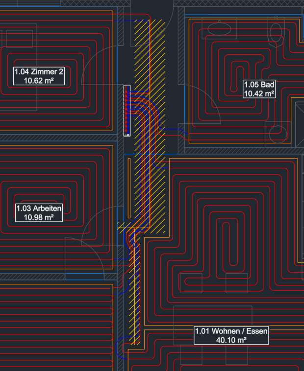
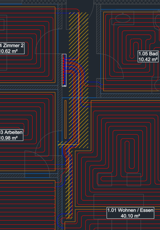
| Automatic | By hand | Through a leader corridor | |
|---|---|---|---|
| How | "All loops of a manifold" or "Individual loops" | "Draw leader by hand", corner by corner | Automatic, but along the corridor you drew |
| Route | bundled along the wall, orthogonal, without crossings | as you click it | bundled in the corridor, branches square to the corridor |
| Follows changes | yes – when a loop is re-placed or the manifold is moved | no – stays as drawn | yes, also a changed corridor (after a question) |
If automatic connecting finds no route around the heated areas, supply and return end together before the first foreign heating pipe – the command line says so, "Check" shows it. You continue by hand. With the setting Leaders in the insulation layer they may run under a heated area. Connecting never changes loops or heated areas.
Leader corridor
A leader corridor is a sketch: a band with a width (1000 mm by default), for example in the hallway or in front of the manifold, in which the automatic leaders run. Its surface is hatched; the heated areas leave it out (after a question). A corridor may have branches. Two corridors that touch or come within 500 mm count as connected when connecting – you need not draw precisely.
Automatic and by hand
Heated areas, loops and leaders are derived: the plug-in rebuilds them when something they depend on changes (room, exclusion area, edge distance, manifold, leader corridor). If you adjust one yourself – with grips, STRETCH, the Properties palette or the tools – it becomes by hand: it then stays that way, even when the room changes. Where that is unambiguous, the partner (supply or return) follows.
Automatic again (tools or Loops page) rebuilds it. "Check" lists everything that is by hand.
Display and layers
Every object type lies on its own layer (room, heated area, exclusion area, loop, supply, return, manifold, leader corridor); color, linetype and lineweight come from the layer by default. Change layer names and colors in the GstarCAD Layer Manager – the assignment stays. A different layer or an own color per type is set under gear menu › Display … – see Display. About layers in general: Layer.
Room tag and loop text
The room tag sits in the room (number and name, by default the area, in a frame). The loop text sits at a loop (number, room, areas, lengths in perimeter and inner zone, leaders, total length). Both are attached to their object and follow it when it changes; their text follows the values. What a new room tag or loop text shows is set in the gear menu – placed ones stay as they are. See Annotate.