
Editing pipes
The tools are below every page of the palette. They act on whole pipes; crossings, rounded corners, elevation change circles, symbols and elevation symbols follow by themselves – in the same undo step.
Selecting several objects
Goal: select the pipes (and other objects) a tool acts on.
- Start a tool – or first select the objects with GstarCAD and then click the button: a preselection applies.
- Click the first object. Each further click adds one, a click on a selected one deselects it. Under the cursor, what a click would hit is highlighted.
- Click next to the objects and drag a selection window – everything inside is selected.
- Enter = done, Esc = cancel (the selection is discarded, the command does nothing).
One piece of a pipe broken at crossings always selects the whole pipe. For Properties the insertion help shows the multiple selection with a picture.
Properties
Goal: change system, system elevation, size, flexible and radius of selected pipes – together with risers and free connectors.
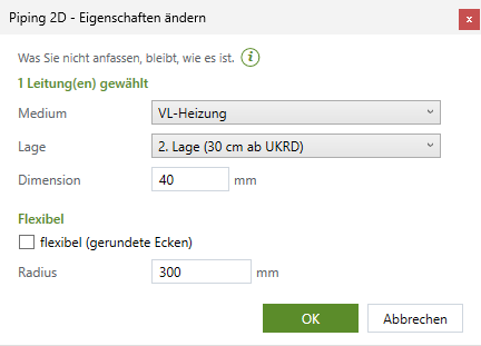
- Click Properties at the bottom and select: pipes, rise/drop symbols and free 2D connectors may be mixed.
- The dialog box shows only the rows that fit the selection: system and size for everything, system elevation, flexible and radius for pipes only, direction and insulation for risers only, the connectors on the right with their own values.
- If the selected objects have different values, the field shows "(unchanged)" or is empty and stays so unless you touch it.
- OK – everything in one undo step. A new system elevation changes the linetype; gaps at crossings and elevation change circles follow. If two pipes of an elevation change have the same system elevation afterwards, the circle disappears.
Special cases: if only a manifold is clicked (or preselected), its manifold dialog box opens; if only connectors are selected, the connector dialog box. The dialog box is explained in detail in the Reference.
Changing the system elevation
Goal: quickly put selected pipes on another system elevation.
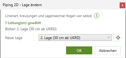
- Click Change system elevation at the bottom and select the pipes (click or selection window); Enter.
- The dialog box names the current system elevation of the pipes ("various" if they differ). The one from the palette is proposed.
- Choose the new system elevation – or take the one of an existing pipe with the Pick button: the dialog box closes, click the pipe, it comes back with that one proposed. "(no system elevation)" removes it.
- OK – linetype, crossings and elevation changes follow by themselves.
Picking system and system elevation
Goal: set the palette to the values of an existing pipe so that the next one matches.
| Pick button | What you click | What is taken |
|---|---|---|
| next to System (Pipe page) | a pipe, a riser or a connector – also inside a block | the system |
| next to System elevation (Pipe and Risers/connectors pages) | a pipe or a free connector with a system elevation | the system elevation; if the pipe has another system, Piping 2D asks: Take the system too or System elevation only |
Esc cancels. While drawing, P and N do the same (see Matching the properties).
Move
Goal: move pipes sideways – the neighbors are shortened, extended or joined again.
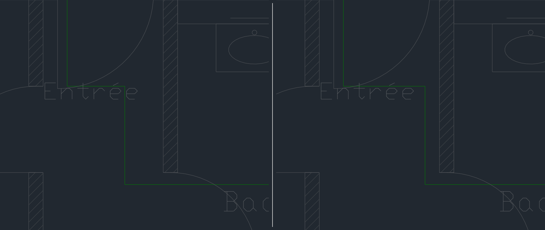
- Click Move at the bottom and select the pipes (click or selection window); Enter.
- Click the new location – the movement runs across the first selected pipe. Or press A and type a distance.
- The neighbors adapt: connected pipes become longer or shorter, a missing joint is created again. If the movement goes past a neighbor, it moves along to the other side.
- A pipe with a symbol takes its whole alignment along – the command line names how many symbols move along.
Keys at the cursor
| Key | Effect |
|---|---|
| Space | one pipe selected: free in plan view or back across; several selected: the next pipe hangs at the cursor |
| G | several selected: free in plan view or back across |
| A | type a distance; several selected: wall offset to the pipe at the cursor |
| ← / → | with a wall offset: switch the side |
A symbol clicked alone is moved along its pipe.
Break
Goal: divide a pipe into two pipes at one point – for example to mark a section differently.
- Click Break at the bottom and click the pipe (it is highlighted).
- Choose the break point on the pipe and click.
- The pipe is divided into two there; a break point remains. The command line names the coordinates.
- Then the next one right away; Enter = finish.
A break point set by hand is never healed by itself – not even when a branch next to it is deleted. Only Connect on both halves makes one pipe again. You cannot break at an end or next to the pipe.
Delete
Goal: remove pipes with their circles and elevation symbols – or a manifold.
- Click Delete at the bottom and select the pipes (click or selection window); Enter.
- The pipes are removed with their elevation change circles and elevation symbols.
- Where a branch was removed, the two halves of the main pipe grow back into one – with equal values and never at a break point set by hand. The command line names the healed locations.
If a manifold is clicked or preselected, it is deleted. The GstarCAD ERASE command does the same.
Editing with grips and GstarCAD commands
Goal: change pipes with the CAD as usual – Piping 2D updates everything attached.
| Command | What Piping 2D updates when it ends |
|---|---|
| end grip, STRETCH | The pipe becomes longer or shorter; the ends attached there move along. |
| middle grip, MOVE | Like Move in the palette: neighbors are shortened, extended or joined. |
| ROTATE, MIRROR | Pipes at a rotated riser, connector or manifold follow it. |
| COPY | The copy pulls nothing along; it is a separate pipe. |
| Properties palette | Change start and end of the line in the GstarCAD fields – this acts like the grip. The LuaCAD category shows the pipe data (system, system elevation, size …) read-only; change them with Properties. |
| ERASE | Like Delete in the palette: the branch is removed, the main pipe heals. |
Crossings, rounded corners, elevation change circles, symbols and elevation symbols follow in the same undo step. A symbol in the pipe has a grip in the middle that slides it along the pipe. If a part is on a locked layer, Piping 2D changes nothing and reports "Layer … is locked".
Check
Goal: count all 2D pipes of the drawing and check them for inconsistencies.
- Click Check at the bottom.
- The command line names: number and length of the pipes, elevation changes, number and length per system and system elevation, risers (of which insulated) and parallel pipes, broken crossings, flexible pipes with rounded and too tight corners, symbols, manifolds and PEX pipes, and the elbows, tees and reducers counted for the list.
- At the end it says "No inconsistencies." or the number of inconsistencies – for example a symbol whose pipe no longer ends at the gap, a PEX pipe at a manifold that no longer exists, or rise/drop symbols that touch. Details are in the log.
Nothing is changed.