
Quick start: your first pipe
This page shows the shortest way to a finished pipe in plan view and the three most common changes afterwards. Every step has a picture; the details are in the linked tasks.
1. Open the palette and choose values
Ribbon › LuaCAD tab › Piping 2D. The palette opens at the edge of the drawing, the first time on the Pipe page.
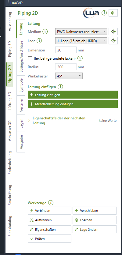
- Choose the system, for example cold water – it sets the color and layer of the pipe.
- Choose the system elevation, for example "1st elevation (15 cm from BOS)" – distance and reference level of the system elevation are in parentheses. If there are no system elevations yet, the list only shows "(no system elevation)" – create them in the gear menu › System elevations. Your first pipe works without one, too.
- Leave the size empty or enter one, for example 20 (mm) – it is used by the bill of materials and the annotation.
- Leave the angle increment at 45° – the pipe then runs in 45° steps.
- Click Insert pipe. Before the first point the insertion help explains the procedure with a picture.
2. Draw the pipe
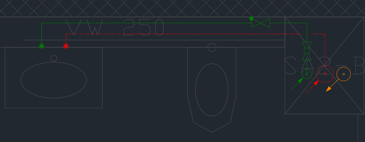
- Click the start into the drawing (1).
- Click the corners (2, 3). The Space key switches between "snap to angle" and "free". A number you type is the length of the next segment in the direction of the cursor.
- Click the end (4) and finish with Enter. With Esc the placed segments stay as well; only the segment at the cursor is dropped.
3. Cross a second system elevation
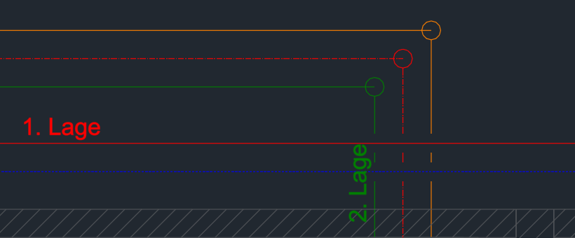
- In the palette choose another system elevation – for example "below the ceiling" – and another system, for example hot water.
- Click Insert pipe and draw a pipe across the first one.
- The pipe on the lower system elevation gets a gap at the crossing (2), the upper one runs through. This happens by itself – later as well, when you move, copy or delete. Which system elevation lies on top is set by the order of the system elevations (see Crossings).
4. Change it with a grip
Picture coming soonPlan view: a pipe selected – grips at the start (1), in the middle (2) and at the end (3)
- Click the pipe – the GstarCAD grips appear at the start, in the middle and at the end.
- Click an end grip, drag it and click at the new location. The pipe becomes longer or shorter; if other pipes end there, their ends move along.
- Crossings, elevation changes and symbols follow by themselves when the command ends.
5. Move
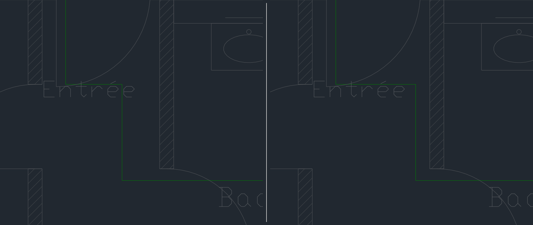
- In the tools at the bottom click Move and click the pipe; Enter.
- Click the new location – or press A and type a distance, for example 250.
- The neighbors are shortened, extended or joined again (2).
More under Move. The GstarCAD commands (MOVE, grips, STRETCH …) work the same way.
6. Change the system elevation
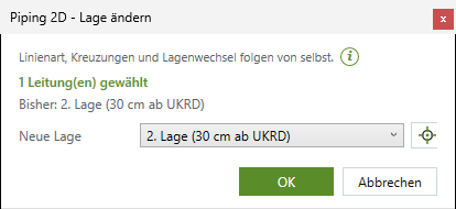
- In the tools at the bottom click Change system elevation and select the pipe; Enter.
- In the dialog box choose the new system elevation – the one from the palette is proposed – and click OK.
- The pipe gets the linetype of the new system elevation; gaps at crossings and elevation change circles follow by themselves.
More under Changing the system elevation.
What next?
Video coming soon: Your first pipe
- Several pipes side by side: Inserting parallel pipes.
- Flexible pipes with rounded corners: Flexible.
- A rise/drop symbol or a connector: Inserting risers, Inserting connectors.
- A valve in the pipe: Inserting a symbol.
- The bill of materials: Output.
- Esc cancels any function; another button in the palette cancels the running command and starts the new one. A U undoes the last step.