
Tools
Picking the base angle
Goal: draw in a skewed floor plan so that the angle increment follows the wall.
- Tools page › Angle › Pick.
- Click two points along a wall (1 of 2, 2 of 2) – their direction becomes the base direction of the angle increment.
- The line below shows the base direction ("base direction 12°"). From now on every duct, round duct and flexible duct run snaps to this direction and its multiples of the angle increment (Parameters page).
- Reset sets the X axis again ("base direction: X axis").
You can also set the base direction in the X-Y and X-Z planes and the increment of both planes in the gear menu › Angle presets. During the run itself W aligns the increment with two clicks, D takes a typed base direction.
Checking for clashes
Goal: find interferences between ducts, round ducts, fittings and devices and the parts of the other plug-ins – on request also with the building elements of an IFC xref.
- Tools page › Clashes section: choose the check set and the scope (this drawing only, against xrefs, also xref against xref).
- Check.
- The list shows each clash once; a click on a row shows the spot in the drawing.
- Accepted, resolved and comments are kept at the next check; what has disappeared is marked resolved.
The check is the same in all plug-ins – details under Piping 3D › Checking for clashes. If the clash detection component is missing, the section is grayed out.
Showing and adjusting insulation
Goal: show or hide all insulation solids, or change insulation material and thickness of many inserted parts.
Show: the switch Visible | Invisible under Insulation shows or hides all insulation solids of the drawing – the highlighted half applies. The data stays; the switch belongs to the drawing (visible by default), undo takes it back with the rest, new parts follow it.
Adjust:
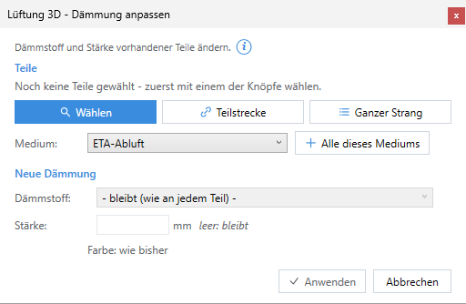
- Adjust under Insulation – the Adjust insulation dialog box opens.
- At the top select the parts: Select (click or selection window), Duct section (click the start and end of a run – all parts in between), Whole network (click a part – everything connected to it) or choose a system and All of this system. The dialog box then comes back with the number of selected parts; they are highlighted in the drawing.
- Insulation material: "- stays (as on each part) -" or an insulation material of the insulation table (with its color).
- Thickness: a number in mm – or empty: then it stays, or with a new material it comes from the table per part (duct or round duct thickness).
- Apply.
Adjusting fabrication parameters
Goal: swap system, catalog, material, air leakage class or hygiene class of many inserted parts – the dimensions stay.
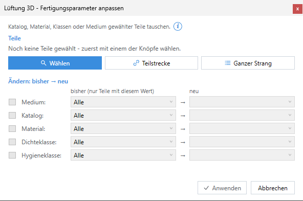
- Adjust under Fabrication parameters.
- At the top select the parts (Select, Duct section, Whole network).
- Per row (system, catalog, material, leakage class, hygiene class) choose on the left the current value – "All" or only parts with this value – and on the right the new one. Choosing "new" switches the row on (check box on the left).
- Below you see how many parts the change affects. Apply.
Checking the duct network
Goal: find open ends, gaps and joints without a counterpart – for example after many changes or before output.
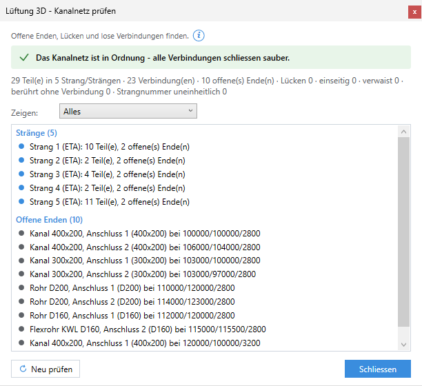
- Check duct network (Tools page › Diagnostics).
- At the top is the verdict – "in order" or the number of errors – below it the counts: parts, networks, joints, open ends, gaps, one-sided, orphaned, touching without joint, inconsistent network number.
- Filter with Show: Everything, Errors only, Networks, Open ends.
- A click on a row zooms there and highlights the parts; the dialog box sits at the left edge so the spot stays visible.
- After a change in the drawing click Check again; Close finishes.
| Finding | Meaning |
|---|---|
| Gaps and kinks | Two parts lie just next to each other but are not joined. |
| Touching but not joined | Two parts meet without being joined. |
| One-sided joints | Only one of the two parts knows the joint. |
| Orphaned joints | The joint points to a part that no longer exists. |
| Inconsistent network number | A connected network carries different numbers. |
| Open ends | Open connectors – not an error, the network can continue there. |