
Drawing ducts and round ducts
Inserting a duct (duct run)
Goal: draw a rectangular duct point by point – LuaCAD places straight pieces, elbows, reducers and transitions by itself.
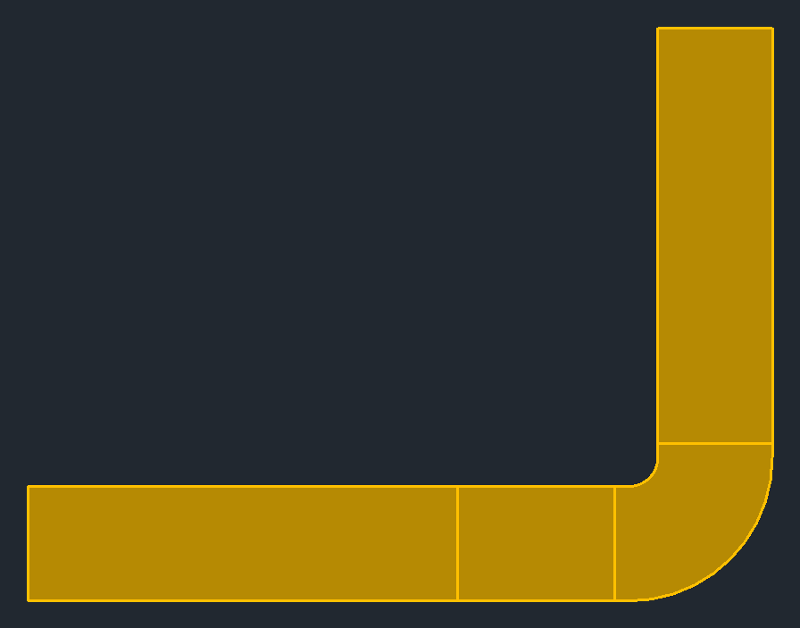
- Ducts page: choose Duct run, set system, justification, A × B, insulation and elevation, then Insert. Before the first run the insertion help appears with a picture.
- Click the start (1): free, at an open connector (the run connects – blue marker – and takes over system, catalog and network) or on an existing duct (a branch with a tee is created there).
- Click further points (2) – an elbow with the radius R and the legs E/F of the palette is created at every corner. A typed number is the length of the next piece in the direction of the cursor.
- Place the last point on an existing duct (3): the tee and the necessary transitions are added by themselves. Or end at an open connector.
- Enter or Esc ends the run – the placed parts stay, the piece at the cursor is dropped.
Keys at the cursor
| Key | Effect |
|---|---|
| A | before the first point: distance to a reference point (see below); during the run: elevation and wall offset in one dialog box |
| Space | during the run: snap to angle (angle increment of the Parameters page) or free |
| W | align the angle increment with a direction by two clicks |
| D | type the base direction of the angle increment (degrees) |
| F | at a connector: hold there or release |
| ← / → / ↓ | draw along the left or right side of the duct, ↓ = centered again |
| ↑ | new centerline: from here on the run follows the centerline of the duct so far, without a jump |
| K | the next reducer centered, flush left or flush right (cycles) |
| B | store the cursor point as a reference point – a typed coordinate 0 takes its value; press again to clear |
| P | the next click matches size and system of a part (places nothing) |
| N | the next click matches only the system |
Before the first point: distance to a reference point
Goal: place the start of a duct exactly at a distance from a wall corner or column.
- After Insert, before the first click, press A.
- In the dialog box enter the amounts X and Y and choose the base point in the 3 × 3 field – the spot of the duct end you hold it by (for example bottom left: then the start lies to the top right of the reference point).
- Click the reference point, for example the wall corner. The start hangs at the cursor once; the Space switches the base point, the distance stays.
- Clicking places the start; then the run continues as usual.
More about distances in all plug-ins: Inserting at a distance.
Elevation and wall offset during the run
Goal: change the elevation in the middle of a run, or route the duct at a fixed distance from a wall.
- During the run press A – the Elevation / wall offset dialog box opens.
- Elevation: enter a new elevation, absolute or from level. From the next point on the duct changes elevation – up to the duct height with an offset fitting, above that with offset elbows (see Elevation change).
- Wall offset: the distance from the drawn line (the wall) to the facing side of the duct. The arrow key ← or → chooses the side the duct lies on. The wall offset applies only to this run.
- OK and keep clicking.
Without the dialog box: the Offset field on the palette below the elevation – a value (for example −300) and Enter or the check mark; at the next click the run steps by this amount at that point. When no run is active, the offset changes the elevation on the palette by the amount.
What the elevation change looks like is set by Elevation change angle below the insulation: Auto (the default) chooses by itself, a fixed angle (90°, 60°, 45°, 30°, 15°) always builds two elbows at that angle. The choice also applies in the middle of drawing.
Drawing along a duct side and reducer alignment
Goal: draw the duct so that the clicked points are one side of the duct instead of its centerline – for example along a wall – and keep reducers flush on one side.
- During the run press ←: the clicked points lie on the left side of the duct (seen in drawing direction); → = right side, ↓ = the centerline again. The button in the action bar cycles the same way.
- ↑ = new centerline: from now on the clicks are the centerline again, continuing from the centerline of the duct so far – without the duct jumping.
- K cycles the next reducer: centered, flush left, flush right. Left/right works only with centered alignment – along a side the side alignment keeps that side flush anyway.
Inserting a round duct (round duct run)
Goal: draw a round (spiral) duct point by point – like a duct, but with diameter D.
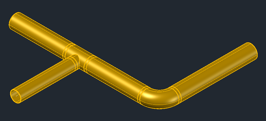
- Round ducts page: choose Round duct run, set system, diameter D, insulation and elevation.
- Choose Branch to duct: on the left the tee with a transition from rectangular to round (low pressure loss, needs space), on the right the round takeoff directly in the duct side (short and simple). This applies when the round duct ends or starts on a duct.
- Insert and click point by point as for the duct; the keys are the same. An elevation change of a round duct sits directly in the corner – the elbows solve corner and elevation at once.
- Enter or Esc finishes.
Inserting a fitting
Goal: insert a single part from the catalog – elbow, tee, offset, reducer, transition, wye, angled branch, takeoff, end cap … – exactly where you want it.
- Ducts (or Round ducts) page: choose Fitting and the part in the list below – the list comes from the catalog and the material of the Parameters page. The picture on the right shows the part with the letters of its dimensions, the preview window shows it in 3D.
- Enter the dimensions (see below) and click Insert. The part hangs at the cursor, held at the base point shown in the preview window.
- Bring it to an open connector: the part connects if the size fits and the system matches the palette – otherwise the marker says what does not fit.
- Point a tee at a straight duct: it is inserted in-line in the whole duct section – click (1 of 2), slide it along, click (2 of 2). Takeoffs and saddles sit on the surface of the duct or round duct (see surface-mounted).
- A click inserts; the next identical part hangs at the cursor. Enter = finish, Esc = cancel.
Keys at the cursor
| Key | Effect |
|---|---|
| F | hold at the connector or release (also the lock on the marker) |
| Z | pull away from the connector – a straight piece is created in between; A asks for the length or the distance to the clicked point |
| R / ↑ / ↓ | connected or on the duct: rotate to the next arm or turn the branch by a quarter; free: rotate with the mouse |
| ← / → | turn around (free: rotate in quarters) |
| D / W | free at the cursor: type an angle / pick it with two clicks |
| T | free at the cursor: tilt in 45° steps |
| Space | show the base points – the next one yellow, a click takes it |
| N | match the system of a clicked part (the click inserts nothing) |
The dimensions of a fitting
The palette shows only the dimension rows the chosen fitting needs; the letters are in the picture on the right. The most important:
| Dimension | Meaning |
|---|---|
| A × B | width × height at the first connector (arrow = swap). |
| C × D | size at the second end (reducing elbow, tee, reducer, wye, angled branch, double elbow). Except for the reducer, C = A. |
| G × H | size of the branch (tee, wye, angled branch); G always equals A. |
| D | diameter of the round end (rectangular-to-round transition). |
| L | length of the part. |
| R, E/F | radius and straight legs of an elbow. |
| W | angle (elbow, angled branch, angled takeoff). |
| −E / −F | edge offset at the second end: −E of the top edges (for offsets of the bottom edges, positive = second end higher), −F of the right side edges. |
| Vertical / lateral position | Whether the ends are flush at the top, center or bottom (or left, center, right) – or free, then −E or −F applies. A typed offset picks the matching position by itself. |
| X / Y | straight ends at the start and the end of a reducer. |
Every row with a crosshair button picks the value from the drawing; the calculator next to a size determines it from the airflow. All dimension rows in detail: Reference › Ducts page.
Connecting two connectors
Goal: join two open connectors (or a connector and a duct) – LuaCAD builds straight pieces, elbows, offsets, reducers and transitions in between.
- Connect (at the bottom of the Ducts or Round ducts page).
- Click the first open connector (1) – the blue marker shows which one applies. Size and system come from it.
- Click the second open connector (2) – or a point on a duct: a tee or a takeoff is created there.
- If there are several routes, LuaCAD shows all of them in color (3). Tab or the right/left arrow switches, the yellow one is selected; a click or Enter accepts, Esc discards.
- Then the next pair right away; Enter = finish.
Duct sizer
Goal: determine the size from airflow and velocity – or the velocity for a given size.
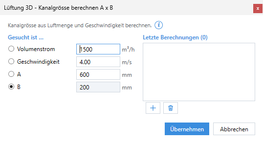
- Click the calculator button next to A × B (or C × D, G × H, D, D2, D3).
- On the left choose what is calculated (the field turns gray); enter the other values, for example an airflow of 1500 m³/h and a velocity of 4 m/s.
- The calculated size is rounded up to the next size of the catalog (without a catalog size: rectangular to 50 mm, round to 10 mm).
- Apply writes the size to the palette and stores the calculation.
Permitted velocity: up to 1000 m³/h 3 m/s, up to 2000 m³/h 4 m/s, up to 4000 m³/h 5 m/s, up to 10 000 m³/h 6 m/s, above that 7 m/s. Beyond that a warning appears. With + you store a calculation in the list on the right (up to 20), a click brings it back, the trash can removes it. Every field calculates ("2*1500").
Picking values
Goal: insert the next part with the values of an existing one instead of typing them.
Many rows have a crosshair button. Click it, then in the drawing:
| Crosshair at | What you click | What is taken over |
|---|---|---|
| System (pick values) | a part | system, catalog, material, insulation and the size at the nearest connector |
| A × B, C × D, G × H, D | a part near the desired end | the size of this connector |
| L, E, L1, distance | two points (1 of 2, 2 of 2) | their distance |
| −E | first the top edge at the first end, then the one at the second | their height difference |
| −F | two points | their horizontal distance |
| W | an elbow or branch | its angle |
| Insulation | a part | insulation material and thickness (applies on this page) |
| Elevation | a point with object snap | its elevation, shown from the chosen reference level |