
Drainage 3D reference
The buttons of the palette
Buttons and tiles that insert something new into the drawing are highlighted or outlined in the color of the plug-in; all others change what is already there. Every button shows a tooltip when you hover over it.
Header and footer (on every page)
| Area / button | Effect | More |
|---|---|---|
| Level | Level for everything you insert from now on; in a project drawing the level of the drawing (locked). | Drainage network |
| System, crosshair | System for everything new (layer and color); the crosshair takes over the system of a clicked object. | Picking the system |
| Insert (Fittings page only) | The chosen fitting or combination to the cursor. | Inserting |
| Generate 3D, Delete 3D | One button for both routing methods – the command recognizes the network from the selection. | Generate 3D, Delete 3D |
| Query and edit properties | On General routing only its objects ("(general)"), on In-wall carrier routing only those of the in-wall carrier ("(in-wall carrier)"), otherwise both. | Properties |
| Move, Delete | Move or delete parts, lines or connectors. | Move, Delete |
General routing page
| Button | Effect | More |
|---|---|---|
| Stack down, Stack up, Fixture, Vent (tiles) | The connector to the cursor. | Inserting connectors |
| Fixture (list) | The template of the Fixture tile. | Templates |
| Fixtures from the Block Library … | Open the Block Library on the Fixtures page. | Block Library |
| Insert line | Draw the plumbing line point by point. | Plumbing line |
| Property fields of the next pipe | Fields every new line gets. | – |
| Slope, % / ° | Slope of new lines. | Slope |
| Edit | Change lines of General routing. | Edit |
| Snap to angle | Base direction of the angle increment with two clicks. | Snap to angle |
| Delete, Delete all | Delete lines; all of the level and system (with a confirmation). | Deleting lines |
| Standard | Display of the standard (set in the gear menu › Options › Sizing). | Standard |
| DN | Only "no standard": diameter for all pipes. | Generate 3D |
| Reducer: eccentric, concentric | How reducers lie when generating 3D. | Reducer |
| Generate 3D, Delete 3D | As in the footer. | Generate 3D |
In-wall carrier routing page
| Button | Effect | More |
|---|---|---|
| Stack (tile), DN, product line | The stack of the in-wall carrier with diameter and product line. | Stack |
| Stack dialog box when inserting | Show the stack dialog box after placing. | Stack |
| Stack across levels › To | Project only: down to which level below. | Across levels |
| Elevation (of the horizontal branch), value, crosshair | Automatic or fixed invert at the connector. | Horizontal branch |
| Fixture (tile), fixture, product line, DN | The chosen fixture onto the line. | Fixture |
| Connector dialog box when inserting | Show the connector dialog box after placing. | Connector dialog box |
| Fixtures from the Block Library … | Open the Block Library on the Fixtures page. | Block Library |
| Insert line, slope | Draw the carrier line. | Carrier line |
| Edit, Delete | Change or delete objects of the in-wall carrier. | Edit |
| Standard, Generate 3D, Delete 3D | As on General routing. | Generate 3D |
| Move stack across all levels | The stacks of the same name go along. | Move |
Connectors page
| Button | Effect | More |
|---|---|---|
| Type (tiles) | Stack down/up, fixture, vent, offset, spot elevation. | Types |
| Template, +, pencil, recycle bin | Choose a template, create (copy), edit, delete. | Templates |
| Stack across levels › To | Project only: how far the stack reaches. | Across levels |
| Show properties before inserting | Property fields before the cursor, the connector dialog box after placing. | Connector dialog box |
| Angle | Offset only: angle of new offsets. | Offset |
| Insert … | The connector of the chosen type to the cursor (the text names the type). | Stack, Fixture |
| Base point: choose in the preview | Base point and distance before inserting. | Base point |
| In the drawing: Edit, Delete | Change or delete inserted connectors. | Edit |
Fittings page
| Button | Effect | More |
|---|---|---|
| Manufacturer, product line | Where the fittings come from. | Product line |
| Connect two ends | Pipe, offset or reducer between two free ends. | Connect |
| Method: Single, Combination | One fitting or several together. | Single, Combination |
| Shape, type, size, automatic, 2nd size | The single fitting. | Single |
| Shorten | Fully shorten a free connector of a fitting. | Shorten |
| Combination, spacing, X dimension, legs, size, 2nd size, outlet | The combination. | Combination |
| Insert (footer) | The chosen part to the cursor. | Inserting |
Custom parts page
| Button | Effect | More |
|---|---|---|
| Folder, "…" | Choose a folder or add, rename, remove folders. | Custom part |
| Show properties before inserting | Property fields before the cursor. | Custom part |
| List, picture | The parts with a connector; the picture of the selected one. | Custom part |
| Open part, Show in folder | Only for a DWG without a connector. | Defining connectors |
| Top edge, Fixed elevation when inserting freely | Elevation of freely inserted parts. | Custom part |
| Insert | The part to the cursor. | Custom part |
| Define connectors, Open folder | Wizard in the open DWG; folder in Explorer. | Defining connectors |
Accessories page
| Button | Effect | More |
|---|---|---|
| Electrofusion coupling › Insert, Delete | Coupling onto a pipe or removed. | Electrofusion coupling |
| Supports › Insert, Delete, spacing, Automatic | Clamps one by one or distributed. | Pipe clamps |
| Wall flange › Insert, Delete | Wall flange at a wall penetration. | Wall flange |
| Insulation › Whole network, Single, Network without, Part without, thickness, check box | Add or remove insulation. | Insulation |
| Manhole › Insert | Dialog box, then insert freely. | Manhole |
| Trench drain › Insert | Dialog box, then insert freely. | Trench drain |
Tools page
| Button | Effect | More |
|---|---|---|
| Renumber | Renumber a network. | Renumber |
| Reassign | Level, system, product line of many objects. | Reassign |
| Delete drainage network | A whole network (with a confirmation). | Delete network |
| Error markers › Delete all | Markers out of the drawing. | Error markers |
| Check 3D | Look for gaps in the 3D. | Check 3D |
| Divide objects across levels … | Distribute what reaches across a dividing plane to the levels. | Divide across levels |
| Clashes | Rule set, Check, list. | Clashes |
Output page
| Button | Effect | More |
|---|---|---|
| Annotation (tiles) | Type 1, Type 2, Type 3, Type 2 cut, Qww, spot elevation, stack, fixture, slope, manhole, center to center. | Annotation |
| Edge, Reference, Annotate elevation | Only with the Spot elevation tile. | Spot elevation and elevation |
| Single, All, Move, Delete | Place and change annotations. | Annotation |
| Annotation from template › Annotate, Templates …, Several …, Edit, Check, Reassign | Annotations from template. | From template |
| Detail › Detail, All, Move, Delete | Details of the nodes. | Detail |
| Parts list, Bill of materials (each with Per network and gear) | Lists in the drawing or a file. | Lists |
| Bill of materials across the project …, across xrefs … | Lists across several drawings. | Across drawings |
| Fittings | Which fittings get numbers. | Fittings |
| Evaluate visible objects only | Layers that are off in no list. | Lists |
| Cut list | Cutting to stock lengths. | Cut list |
All keys at the cursor
The same key means the same in every plug-in. The action bar shows which keys apply; Shift and Ctrl are never assigned at the cursor.
| Key | Meaning in Drainage 3D |
|---|---|
| A | before placing: distance to a reference point; while drawing: slope, elevation, wall offset and fixed length; when moving: type a dimension |
| Space | while drawing snap to angle / free; for a connector line snap off/on or (with a distance) next base point; for a fitting show the connectors; when moving free in plan |
| L | line snap off/on while the Space key switches the base point |
| E | values of the next connectors |
| R | rotate a fitting (connected: next arm); turn the arrow of an in-wall carrier fixture by 90° |
| H | centerline elevation of an in-wall carrier fixture; when moving elevation only |
| L / Q | when moving along only / across only |
| D | type an angle (degrees) |
| W | pick an angle – always two clicks |
| F | hold a fitting at the connector |
| Z | pull a fitting away – a pipe in between; back = shorten |
| P | while drawing: take over system and slope of a clicked plumbing line |
| N | take over only the system |
| Arrow keys | rotate a fitting by 90°; with a wall offset switch the side |
| Tab | next solution (Connect two ends) |
| Enter | done or apply |
| Esc | cancel – while drawing, the segments already placed stay; in a dialog-based process (manhole, Reassign) back to the dialog box |
The gear menu
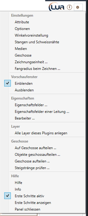
| Entry | Effect |
|---|---|
| Settings › Attributes | Appearance of connectors, plumbing lines, pipes, insulation, clamps, manholes, annotation, spot elevation, slope, item numbers, lists and error markers – each "by system" or its own. Dialog box |
| Settings › Options | Snapping, Generate 3D, Sizing, Connectors and fittings, Annotation, Editing. Dialog box |
| Settings › Angle presets | Angle offset and angle increment of the plumbing line. Settings |
| Settings › Stock lengths and welds | Stock length and weld loss per product line and diameter, joint between stock lengths. Dialog box |
| Settings › Systems | The system definitions (drainage application). Settings |
| Settings › Levels | The levels of the drawing – the "Level" list at the top of the palette. Settings |
| Settings › Drawing units …, Snap radius while drawing … | Units of new parts; size of the snap circle when drawing the plumbing line. Settings |
| Preview window › Show, Hide | The 3D preview window of the Fittings page; "Show" also brings back a window closed with the cross. |
| Properties › Property fields …, Property fields of a pipe …, Author … | Which fields exist; fields of a whole pipe; the name in lists and IFC. |
| Layers › Create all layers of this plug-in | Creates missing layers; existing ones stay as they are. |
| Levels › Divide across levels …, Divide objects across levels …, Divide across levels settings …, Check risers … | Stacks to the drawings of the levels; dividing plane and switch; check the joints. Across levels |
| Help › Help | This online help. |
| Help › Info, Getting started active, Show getting started | Version and components; cards and insertion help on/off; the cards of the page shown. |
| Close palette | Close the palette – the button on the ribbon shows it again. |
The LuaCAD settings for all plug-ins are on the ribbon › LuaCAD tab › Info – see LuaCAD settings.
Dialog boxes
| Dialog box | Where it opens |
|---|---|
| Options | gear menu › Settings › Options |
| Attributes | gear menu › Settings › Attributes |
| Stock lengths and welds | gear menu › Settings, Options › Connectors and fittings |
| Generate 3D – Result | after "Generate 3D" when there are errors or notes |
| Plumbing line | Edit or Properties on a plumbing line |
| Slope, elevation and wall offset while drawing | A while drawing a plumbing line |
| Connector | after inserting a connector (with the check box), Edit, template |
| Manhole, Trench drain | Accessories page › Insert |
| Reassign objects | Tools page › Reassign |
| Others | questions, part properties, systems, levels, angle, snap radius |
Options
Presets for all drawings: the values apply to everything inserted or generated afterwards; existing 3D changes only at the next "Generate 3D". The defaults usually fit – change only what you need. Six tabs:
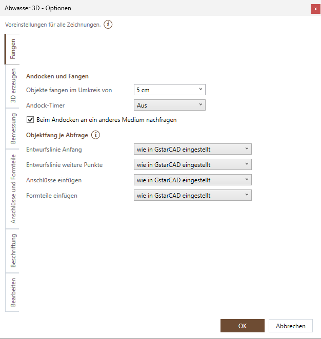
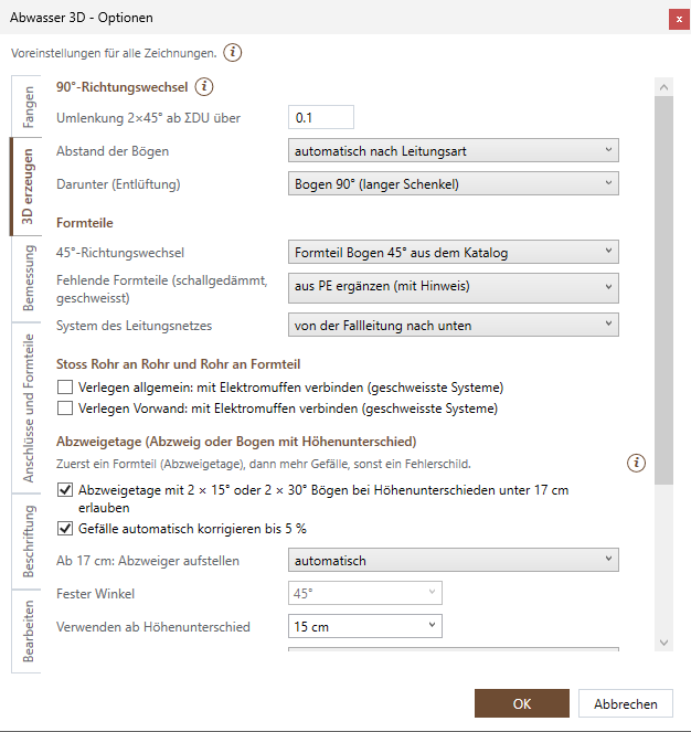
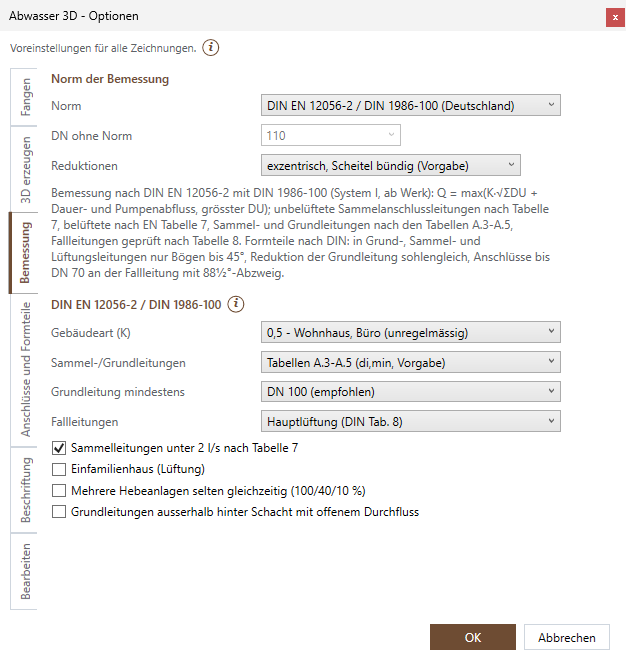
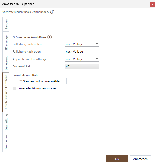
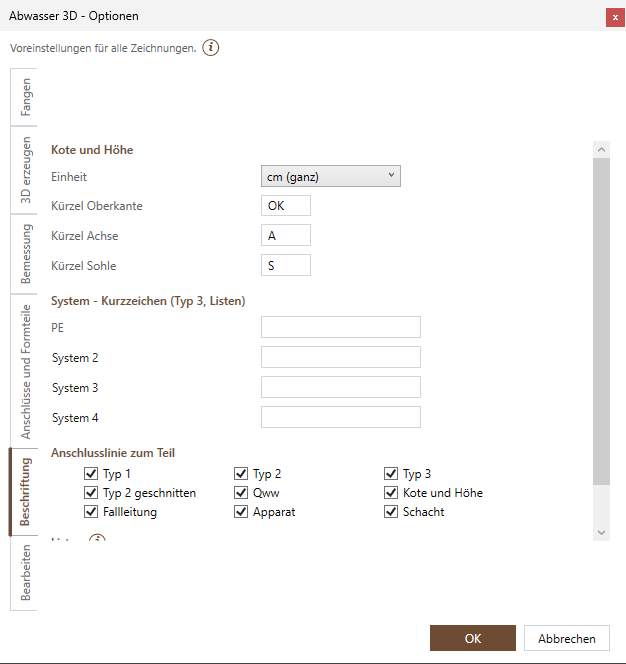
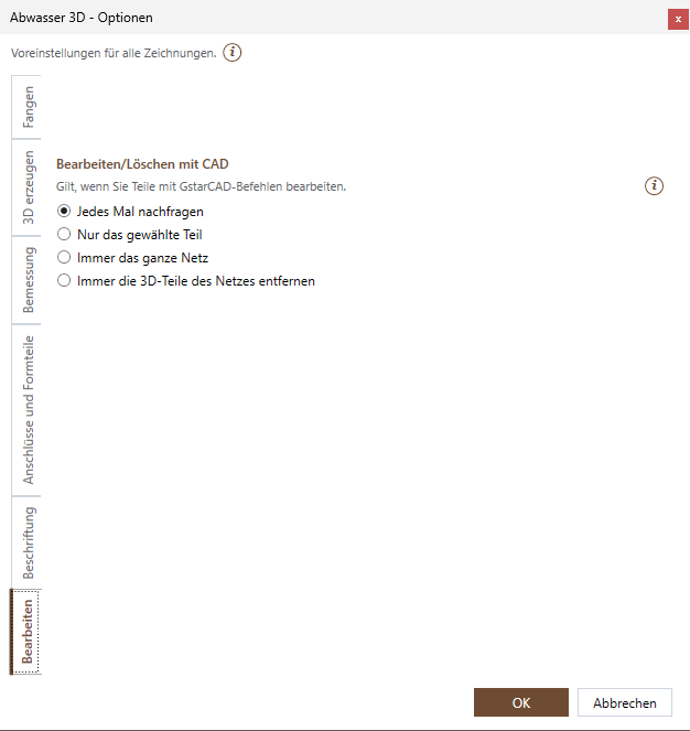
Every setting with its default: gear menu › Options.
Attributes
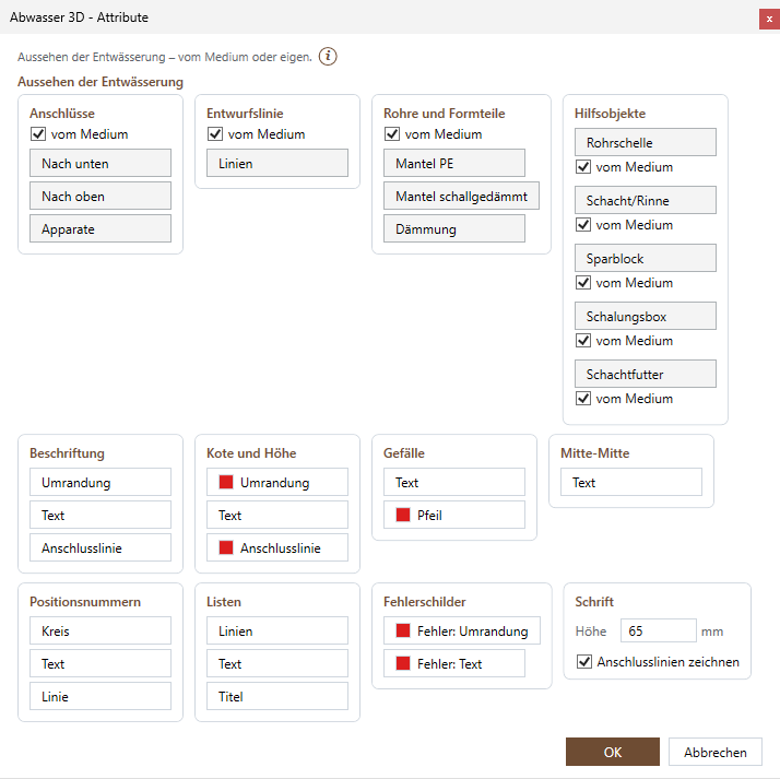
"By system": layer and color come from the system (gear menu › Systems) – so every system carries its color. Without the check box, the own attribute below applies to all systems. Every button opens layer, color, linetype and lineweight. Every setting: gear menu › Attributes.
Stock lengths and welds
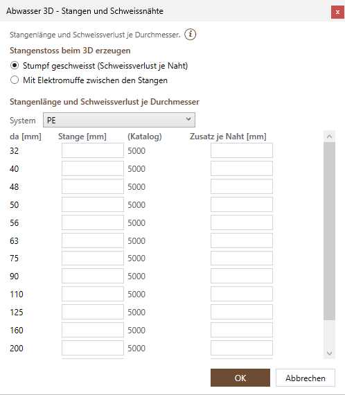
Fused pipes are made up of stock lengths. At the joint of two stock lengths a butt weld is made – the weld loss per weld is deducted from the pipes, the cut list accounts for it – or an electrofusion coupling lies in between. Push-fit product lines have no joint: there "Generate 3D" takes the shortest catalog pipe that is long enough. Every butt weld costs the pipe wall (da – di)/2, half on each side; the table contains only the additional loss per weld. Enter only what differs from the default. Every setting: gear menu › Stock lengths.
Generate 3D – Result
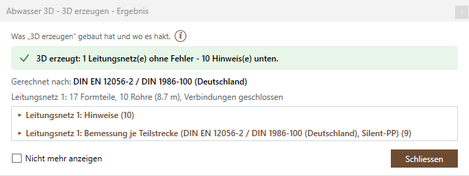
| Part | What it shows |
|---|---|
| Header | green "3D generated: n drainage network(s) without errors" or orange the number of errors |
| Calculated to | the standard used for sizing |
| Figures | per network fittings, pipes (length in m), joints "closed" or "with gaps" |
| Errors (expanded) | red; also as a marker in the drawing |
| Notes (collapsed) | orange; information, for example "More slope" or a part from PE |
| Sizing per section (collapsed) | per section: DN, drain type, ΣDU, Qww in l/s, slope (or vertical), the rule of the standard, number of inlets, path |
| Network check | only with gaps: the places |
| Show | show the place in the drawing (also a click on the row) |
| Apply | only for a slope suggestion: set the slope on the plumbing line(s) and generate the network again |
| Don't show again | switch the window off for Drainage 3D (on again: Options › Generate 3D) |
| Close | close the window |
Plumbing line
| Field | What it does |
|---|---|
| Length in plan, elevation start/end, ΔZ | display only |
| Level | the level of the line |
| System | the system of the line – sets layer and color |
| Slope, % / ° | the slope of the line (takes effect when generating 3D); calculating allowed; at most 100 % (45°) |
| Diameter | "calculate" = "Generate 3D" sizes to the standard; a number = this nominal size (outside diameter in mm) fixed |
| Drain type | fixture drain, branch drain or horizontal branch / building drain – decides the sizing table |
| Carries | wastewater, storm water or air (vent) |
| From "Generate 3D" | display only: ΣDU, Qww and the built diameter |
Slope, elevation and wall offset while drawing
| Field | What it does | Default |
|---|---|---|
| Slope, % / ° | slope of the next segment; also goes to the palette | from the palette (2 %) |
| Elevation, crosshair | elevation at the current point: before the first segment the start of the line, afterwards an elevation change (vertical line); the crosshair picks an elevation | the current elevation |
| Wall offset, side | the line runs at this distance next to the drawn one; applies only to this run (not in the in-wall carrier) | 0 |
| Fixed length | 0 = with the mouse; otherwise OK inserts a segment of this length in the current direction | 0 |
Connector
One dialog box for all types; what does not apply to the choice is hidden. In template mode the name of the template is at the top; level and system come from the palette when inserting.
| Section › field | For | What it does |
|---|---|---|
| Routing | fixture from the Block Library | In-wall carrier or below ceiling / in the floor – switching places the connector again after OK from the template of the other routing. |
| Template › name | stacks, fixture, vent | Choose another template: all values below come from it (position, level and system stay). |
| Template › short name | the same | Short name in annotations and lists. |
| Assignment › level, system | all except offset and spot elevation | What the connector belongs to (offset and spot elevation take it from their line). |
| Product line › manufacturer, product line | stacks, fixture, vent | The pipe product line of the connector. |
| Product line › diameter or stack pipe, outlet | the same | Diameter as a minimum ("Generate 3D" never sizes smaller); the outlet of the stack down ("auto" = from the sizing). Some fittings only exist in fixed diameters. |
| Fixed size (independent of the calculation) | stack down | The stack pipe gets exactly the chosen diameter; if the calculation gives more, a note appears. Default off. |
| Fittings › continuation above | stacks, fixture, vent | What follows above the main fitting (nothing, pipe, push-fit coupling, long coupling, formwork box, blockout …), plus extension and the dimensions of a box. |
| Fittings › main fitting | the same | The part at the connector: wye, elbows, double 45° bend, straight, floor drain, roof drain, fitting by hand … |
| Fittings › blockout | where selectable | Provide a blockout at the main fitting – the dimensions (length, width, height, horizontal/vertical offset, insertion depth) appear below. |
| Fittings › fully shortened | stack down | Shorten the main fitting as far as the catalog allows. |
| Fittings › continuation below, extension or shortening | stack down | What follows below the main fitting. |
| Fittings › bottom of fitting instead of invert | stack down | The invert elevation applies to the bottom of the lowest fitting. |
| Fittings › connect without branch offset | stacks, fixture, vent | No raised wye and no offset of two elbows – the outlet goes straight up. |
| Elevation › top or installation elevation, invert | stacks, fixture, vent | automatic (from the slope), from TOS, from BOS (downward), absolute, for stacks also "from the fittings"; plus == exactly, >= at least, <= at most, the value and the crosshair. |
| Spot elevation › spot elevation here, relative to | spot elevation | absolute, from TOS or from BOS with ==/>=/<= and value; top, centerline or invert. |
| Offset › angle, position, offset, automatic | offset | 30/45/60/90°; before the connector, exactly at the connector, after the connector; offset fixed or "automatic" from the elevations. |
| Drainage network › building drain | stack down | as the inlets (preset), inside the building, outside the building, outside behind a manhole with open flow – effective only under DIN. |
| Load from above › calculation | stack up | floor-level branch, building drain, storm water, horizontal branch, building sewer. |
| Load from above › pumped discharge line (downward connector) | stack up | The inlet is a pumped discharge line. |
| Load from above › double bend | stack up | fitting to fitting, 2 × inside diameter, 3 × inside diameter. |
| Load from above › sum of DU or flow Q, fixtures, individual fixtures … | stack up | The load in l/s; or up to ten fixture types with quantity – sum of DU, quantity and largest single DU are calculated from them. |
| Load from above › Qww, enter load as Qww, K value, continuous flow | stack up, building drain/horizontal branch | The load directly as Qww; frequency factor K (0.5/0.7/1.0/1.2); continuous flow in l/s. |
| Load from above › stack height | stack up, DIN only | How high the stack is above this connector (m; empty = up to 10 m): above 10 m a double bend of two 45° elbows with a 250 mm piece in between, above 22 m a bypass. |
| Vented | fixture, stack up | Sizing with the table for vented pipes. Default on. |
| Connector › DU | fixture | Discharge unit in l/s (at least 0.05). |
| Connector › custom part | fixture | A DWG instead of the main fitting (list from the folder of the Custom parts page). |
| Connector › offset, electrofusion coupling, supplied | fixture with floor drain/inlet | none/45°/90°; none/at the outlet/at the offset; the generic standard or the version with a product name. |
| Connector › relief vent (downward connector) | vent | The vent as a relief vent. |
| Axial offset | fixture, vent | Offset of the connector along the axis. |
The connector dialog box of an in-wall carrier fixture is described under In-wall carrier routing, that of the stack of the in-wall carrier under Stack of the in-wall carrier.
Manhole
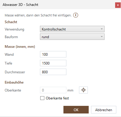
| Field | What it does | Default |
|---|---|---|
| Use | inspection chamber, pump sump, silt trap, oil separator | inspection chamber |
| Shape | round, round with neck (cone), rectangular, rectangular with neck – only the matching dimensions appear | round |
| Wall | wall thickness | 100 mm |
| Depth | inside depth | 1500 mm |
| Diameter or length | round: diameter; rectangular: length (inside) | 800 mm or 1000 mm |
| Width | rectangular only | 800 mm |
| Neck height, neck diameter or neck length, neck width | with neck only; the neck must be lower than the depth and narrower than the manhole | 600 / 625 / 625 mm |
| Eccentric neck (flush with the wall) | round with neck only | off |
| Top edge, crosshair | the installation elevation; when picked it applies as fixed | 0 |
| Fixed top edge | unchecked, the top edge lies at the elevation of the cursor (drawing plane or object snap) | off |
The dimensions are in drawing units; the values are kept for the next manhole.
Trench drain
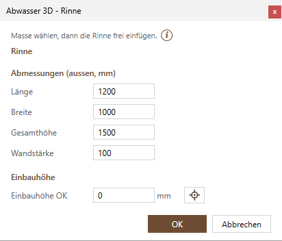
| Field | What it does | Default |
|---|---|---|
| Length, width | outside dimensions of the trench drain | 1200 / 1000 mm |
| Total height | outside height, with bottom | 1500 mm |
| Wall thickness | length and width must be greater than twice the wall thickness | 100 mm |
| Installation elevation of the top, crosshair | the top; always fixed | 0 |
Reassign objects
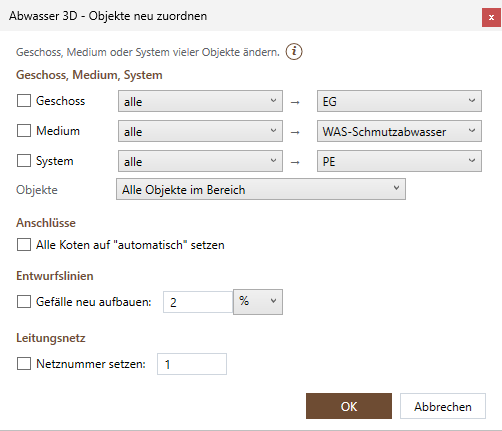
| Field | What it does | Default |
|---|---|---|
| Level, system, product line (check box, old → new) | What should change; "old" = "all" or only objects with this value, "new" = the new value | off; new = palette value |
| Objects | all objects in the area, only parts (pipes, fittings, accessories), only plumbing lines and connectors | all objects in the area (remembered) |
| Set all spot elevations to "automatic" | top and invert of stacks and fixtures to automatic – the elevation comes from the plumbing line again | off |
| Rebuild slope, value, % / ° | Set the slope of all selected lines and rebuild the elevations from the stack; then generate the 3D again | off; value from the palette |
| Set network number | Give all selected objects this network number | off; the next free one |
Other dialog boxes
| Dialog box | Purpose |
|---|---|
| Delete (question) | Delete only the selected, Delete 3D or Delete whole drainage network; "Remember answer". |
| Drainage network with 3D parts changed | Generate 3D again, Delete 3D or only the change; "Remember answer" (for CAD commands). |
| Different system | A fitting is about to connect to a different system: Connect or Cancel; "Remember answer". |
| Branch offset | Only with "ask" (Options › Generate 3D): at the first raised wye of a run the angle with a preview. |
| Properties (parts) | Product line, DN, angle, length, what stays, insulation, system, level – see Properties. |
| Fixtures of the stack up | Up to ten fixture types with quantity for the load from above. |
| Systems, Levels, Angle presets, Snap radius, Drawing units | See Every setting in detail. |
Every setting in detail
This section lists every setting of Drainage 3D – on the palette, in the gear menu and in the dialog boxes – with its effect, the default value and an example. Values on the palette apply only to parts you insert afterwards. Settings in the gear menu apply to all drawings. Lengths are typed in drawing units; every number field calculates ("600+400" becomes 1000).
Palette, header
| Setting | What it does | Default | Example |
|---|---|---|---|
| Level | Level of new objects; in a project drawing the level of the drawing (locked). Create levels: gear menu › Levels. | Not assigned | "EG - ground floor" |
| System | System of new objects – layer and color; only the same system connects. | first drainage system | storm water for the roof drainage |
Palette, General routing page
| Setting | What it does | Default | Example |
|---|---|---|---|
| Fixture | Template of the Fixture tile. | first template | "toilet" |
| Property fields of the next pipe | Fields for every new plumbing line. | no values | construction phase "B" |
| Slope | Slope of new lines, takes effect when generating 3D. | 2 | 1.5 for a building drain |
| % / ° | Unit of the slope; switching converts. | % | ° for a value in degrees |
| DN (no standard only) | Diameter of all pipes. | 110 | 125 |
| Reducer | eccentric (top flush) or concentric (centerline continues). | eccentric | concentric |
Palette, In-wall carrier routing page
| Setting | What it does | Default | Example |
|---|---|---|---|
| DN (stack) | Diameter of the stack pipe (nominal sizes of the product line). | 110 | 90 |
| Product line (stack) | Pipe product line for stack pipe and horizontal branch of the in-wall carrier network. | product line of the Fittings page | a fused product line |
| Stack dialog box when inserting | Dialog box after placing; unchecked, the last values apply. | on | off for many identical stacks |
| To (stack across levels) | Project only: down to which level below. | this level only | down to the basement |
| Elevation (horizontal branch) | automatic, fixed above FF, fixed above TOS, fixed absolute. | automatic | fixed above TOS, 120 |
| Value, crosshair | The fixed invert at the connector; applies with Enter. | 0 | 150 |
| Fixture | Which fixture is inserted next. | toilet | lavatory |
| Product line (fixture) | "as stack" or a fused product line of its own, remembered per fixture. | as stack | – |
| DN (fixture) | Diameter of the connector, remembered per fixture; fixed for the back-to-back fitting. | per template | 56 for the sink |
| Connector dialog box when inserting | Dialog box after placing; unchecked, the last values apply. | on | – |
| Slope (line) | Slope of new lines of the in-wall carrier in %. | 2 | 1 |
Palette, Connectors page
| Setting | What it does | Default | Example |
|---|---|---|---|
| Type | Which type "Insert …" places. | stack down | fixture |
| Template | Template per type (remembered). | first template | "shower" |
| To | Stack across levels, remembered per direction. | this level only | up to the 3rd floor |
| Show properties before inserting | Remembered per type. | on | off when the template fits |
| Angle (offset) | Angle of new offsets (also in the gear menu › Options). | 45° | 30° |
Palette, Fittings page
| Setting | What it does | Default | Example |
|---|---|---|---|
| Manufacturer, product line | Catalog of the fittings. | first manufacturer, first product line | a sound-insulated product line |
| Method | Single or Combination. | Single | Combination |
| Shape, type | The fitting. | wye | elbow |
| Size | Outside diameter. | 110 | 75 |
| automatic (Single) | When connecting, the DN of the connector. | on | off for a deliberate reducer |
| 2nd size | Second diameter or angle. | as size | 50 |
| Combination | Which combination. | double 45° bend | branch offset wye-elbow |
| Spacing | Distance of the parts. | fitting to fitting | 2 × inside diameter |
| X dimension | Distance with "manual". | 0 | 120 |
| Legs | L-L, S-L, S-S. | L-L (long-long) | S-S |
| Size, automatic (Combination) | Diameter; "automatic" as for Single. | 110, off | – |
| Outlet | parallel (0°), upward, 45° to the side, 90° to the side. | parallel (0°) | upward |
Palette, Custom parts page
| Setting | What it does | Default |
|---|---|---|
| Folder | Which folder the list comes from. | Examples / special parts |
| Show properties before inserting | Property fields before the cursor. | off |
| Top edge | Elevation above FF when inserting freely. | 0 |
| Fixed elevation when inserting freely | Checked, the elevation above; unchecked, that of the cursor. | on |
Palette, Accessories page
| Setting | What it does | Default | Example |
|---|---|---|---|
| Spacing (supports) | Largest clamp spacing for "Automatic"; 0 = horizontal 10 × da, vertical 15 × da. | 0 | 1000 |
| Thickness (insulation) | Insulation thickness in mm. | 25 | 40 |
| Insulate when generating 3D and inserting | Insulate new pipes and fittings right away. | off | on for a storm water pipe in a heated space |
Palette, Output page
| Setting | What it does | Default | Example |
|---|---|---|---|
| Annotation | Which tile "Single" and "All" place. | Type 1 | slope |
| Edge | Top, centerline or invert (spot elevation and "Annotate elevation"). | invert (S=) | centerline |
| Reference | FF, TOS, BOS or absolute. | FF (finished floor) | absolute |
| Fittings | only shortened/cut or all fittings get numbers; switching renumbers. | only shortened/cut | all fittings |
| Evaluate visible objects only | Layers that are off or frozen do not go into the lists. | off | on |
Gear menu › Options
| Tab › setting | What it does | Default | Example |
|---|---|---|---|
| Snapping › Snap to objects within | How close to the cursor a part snaps to a free connector, a connector to the end of a line, a line to a line (cm; with "mm" in mm; from 0.5 cm). | 5 cm | 10 cm in a dense drawing |
| Snapping › Connect timer | If connected this long, a fitting is held as with F; Off = only with the key. | Off | 0.8 s |
| Snapping › Ask when connecting to a different system | Question Connect/Cancel; off = connect without a question. | on | – |
| Snapping › Object snap per prompt | Per prompt (plumbing line start, plumbing line further points, inserting connectors, inserting fittings) an object snap of the CAD for the duration of the prompt. | as set in GstarCAD | endpoint and intersection for the start |
| Generate 3D › Double 45° bend above ΣDU | Above this load a 90° change of direction becomes a double bend of two 45° elbows; a large number = always a 90° elbow. | 0.1 | 1.0 |
| Generate 3D › Spacing of the elbows | automatic by drain type (building drain 3 × inside diameter, otherwise fitting to fitting), fitting to fitting, 2 × or 3 × inside diameter. | automatic by drain type | 2 × inside diameter |
| Generate 3D › Below (vent) | Up to this load: 90° elbow (long leg), double bend fitting to fitting or with 3 × inside diameter. | 90° elbow (long leg) | – |
| Generate 3D › 45° change of direction | Catalog 45° elbow or cut from a 90° elbow (PE only). | catalog | cut |
| Generate 3D › Missing fittings (sound-insulated, welded) | If the sound-insulated welded product line does not include a fitting: add it from PE (with a note) or an error marker. | add from PE | error marker |
| Generate 3D › Product line of the drainage network | Which product line the whole network gets: from the fixtures (most inlets) or from the stack down. | from the stack down | from the fixtures |
| Generate 3D › General routing / In-wall carrier routing: connect with electrofusion couplings | At every joint pipe to pipe and pipe to fitting an electrofusion coupling instead of butt fusion (fused only; if the coupling is missing or the pipe is too short, it is fused). | off | on |
| Generate 3D › Allow branch offset with 2 × 15° or 2 × 30° elbows … below 17 cm | Below 17 cm difference in elevation first the branch offset of two catalog elbows. | on | – |
| Generate 3D › Correct slope automatically up to 5 % | If no fitting fits: the branch pipe falls more steeply, at most 5 %, with a note marker; off = error marker. | on | – |
| Generate 3D › From 17 cm: raise the wye | automatic (the 45° wye is raised so far that a 60° elbow, or 30° on the 45° branch, leads exactly into the upper pipe), ask (dialog box with preview at the first such branch), fixed angle. | automatic | ask |
| Generate 3D › Fixed angle | Only with "fixed angle": none, 30°, 45°, 60°, 75°, 90°. | 45° | 60° |
| Generate 3D › Use from difference in elevation | From this difference the raised wye; below it straight up or (with "first a fitting") the branch offset of two elbows, then more slope. | 15 cm | 20 cm |
| Generate 3D › Small difference in elevation | first a fitting, then slope (recommended) or only from the difference, otherwise vertical. | first a fitting | – |
| Generate 3D › Raise side wyes by 15° | A wye with a horizontal inlet from the side is turned up by 15° – against backflow; the inlet lies slightly higher. | off | on |
| Generate 3D › Different system/level | If a line starts at existing objects in a different system or level: take over from the existing objects, keep the palette (with a note), ask every time. | ask every time | take over from the existing objects |
| Generate 3D › Switch the helper layer … off again | Anyone who switched on the helper layer of the hidden lines to look gets it switched off again after the next "Generate 3D". | on | – |
| Generate 3D › Show list after generating | The result window after "Generate 3D". | on | – |
| Sizing › Standard | DIN EN 12056-2 / DIN 1986-100 (Germany), SN 592 000 (Switzerland), no standard – DN by hand. If a table of the standard is missing in the catalog, the note says so, and "Generate 3D" places an error marker naming the other standard as a way out. | DIN EN 12056-2 / DIN 1986-100 | SN 592 000 for a project in Switzerland |
| Sizing › DN without standard | Nominal size of all pipes without a standard. | 110 | 100 |
| Sizing › Reducers | eccentric, crown flush, or concentric (as on the palette). Under DIN an eccentric reducer in the building drain lies flat on bottom; with "concentric" the result names the DIN rule as a note. | eccentric | – |
| Sizing › Building type (K) | DIN only: frequency factor 0.5 / 0.7 / 1.0 / 1.2 (laboratory, EN only). | 0.5 | 0.7 for a school |
| Sizing › Horizontal branches/building drains | DIN only: Tables A.3–A.5 (di,min) or Prandtl-Colebrook with the catalog di (often one size smaller). | tables | Prandtl-Colebrook |
| Sizing › Building drain at least | DIN only: DN 100 (recommended) or DN 80 (with a note). | DN 100 | – |
| Sizing › Stacks | DIN only: primary ventilation (DIN Table 8) or secondary ventilation (EN Table 12). | primary ventilation | – |
| Sizing › Horizontal branches below 2 l/s per Table 7 | DIN only. | on | – |
| Sizing › Single-family house (ventilation) | DIN only: the collective main vent need not be one nominal size larger. | off | on |
| Sizing › Several lifting stations rarely at the same time | DIN only: largest 100 %, second 40 %, others 10 %. | off | – |
| Sizing › Building drains outside behind a manhole with open flow | DIN only: full flow per Table A.5. | off | – |
| Connectors and fittings › Size of new connectors | Sphere diameter of the display per stack down, stack up, fixtures and vents (cm; "per template"). | per template | 20 cm |
| Connectors and fittings › Offset angle | Angle of new offsets. | 45° | 30° |
| Connectors and fittings › Stock lengths and welds … | Opens the Stock lengths dialog box. | – | – |
| Connectors and fittings › Allow extended shortening | Not available – shortening goes up to the shortening of the catalog. | off (locked) | – |
| Annotation › Unit | Unit of the spot elevation and the elevation annotation: cm (whole), m (two decimals), mm (whole). | cm | m |
| Annotation › Short code top / centerline / invert | Code before the spot elevation. | OK, A, S | UK instead of S |
| Annotation › Product line - short code | How a product line appears in Type 3 annotation and in the lists; empty = its name. | empty | "PE-HD" |
| Annotation › Connecting line to the part | Per type (Type 1, Type 2, Type 3, Type 2 cut, Qww, spot elevation and elevation, stack, fixture, manhole) a line to the part. | on | off for Type 3 |
| Annotation › Lists: Parts list …, Bill of materials … | Set the output of the lists. | – | – |
| Editing › Editing/deleting with CAD | When a part of a network is selected, moved, copied or deleted with the CAD commands: ask every time, only the selected part, always the whole network, always remove the 3D parts of the network. Also applies when deleting from the palette. | ask every time | always the whole network |
Gear menu › Attributes
| Card › button | What it controls | Default |
|---|---|---|
| Connectors › by system, Down, Up, Fixtures | Appearance of the connectors stack down/up and fixture. | by system |
| Plumbing line › by system, Lines | Plumbing line, vent, offset, spot elevation. | by system |
| Pipes and fittings › by system, PE jacket, jacket (sound-insulated product line), insulation | Bodies and insulation shell (color and transparency). | by system |
| Helper objects › pipe clamp, manhole/trench drain, blockout, formwork box, shaft sleeve | each with "by system". | by system |
| Annotation › frame, text, connecting line | Annotations of the tiles. | by CAD |
| Spot elevation and elevation › frame, text, connecting line | Spot elevations. | frame and line red |
| Slope › text, arrow | Slope annotation. | arrow red |
| Center to center › text | Center-to-center dimension. | by CAD |
| Item numbers › circle, text, line | Item numbers. | by CAD |
| Lists › lines, text, title | Tables in the drawing. | by CAD |
| Error markers › error: frame, error: text | Markers of "Generate 3D". | red |
| Text › height | Text height of item numbers and annotations (center to center slightly smaller). | 65 mm |
| Text › draw connecting lines | On and off for all types; per type in Options › Annotation. | on |
Gear menu › Angle presets
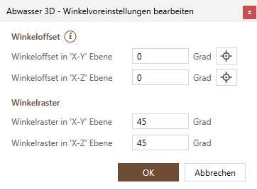
| Setting | What it does | Default | Example |
|---|---|---|---|
| Angle offset X-Y / X-Z | How far the angle increment is rotated (plan or vertical); the crosshair picks it with two clicks. "Snap to angle" on the palette does the same. | 0° | 12° for an inclined building |
| Angle increment X-Y / X-Z | Step of the increment when drawing the plumbing line. | 45° | 15° |
Gear menu › Stock lengths and welds
| Setting | What it does | Default | Example |
|---|---|---|---|
| Joint when generating 3D | Butt fused (weld loss per weld) or with an electrofusion coupling between the stock lengths. | butt fused | electrofusion coupling |
| Product line | Which product line the table applies to (all product lines of the catalog). | product line of the Fittings page | – |
| Stock [mm] per da | Stock length per outside diameter; empty = the longest catalog pipe (column "(catalog)"). | empty | 5000 |
| Extra per weld [mm] per da | Additional weld loss per weld (both sides together); the pipe wall always counts already. Locked for push-fit. | empty = 0 | 2 |
Gear menu › Systems
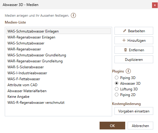
The system definitions with the drainage application: create and change systems, their appearance per position – stack down, stack up, fixtures, plumbing line and connectors, pipe centerline, PE body, sound-insulated body (by default the same as the PE body – by layer of the system) and insulation (color and transparency, default 80 % by layer). A change "by layer" goes to the layer of the current drawing. More under Systems and System and layer.
Gear menu › Levels
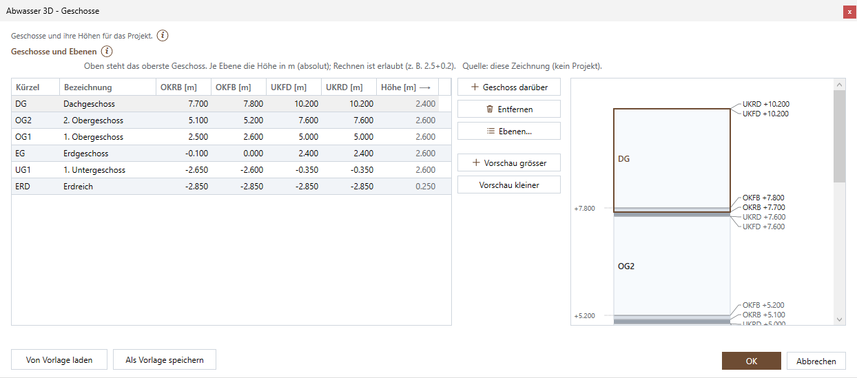
Per level code, name and the elevations of the reference levels TOS, FF, FC, BOS. The levels appear in the Level list at the top of the palette. A change never moves an object. More under Levels and system elevations and Level.
Gear menu › Drawing units and snap radius
| Setting | What it does | Default | Example |
|---|---|---|---|
| Drawing units … | In which units new parts go into the drawing and the fields show lengths: automatic (from the drawing), mm, cm, dm, m. Applies to all plug-ins. | automatic | cm for a drawing in cm |
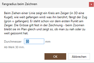
| Snap radius while drawing … | Diameter of the circle (in 3D the sphere) at the cursor within which drawing the plumbing line snaps to lines and connectors; fixed in the drawing, keeps its size on the sheet when zooming. | 30 mm | 60 mm |
Connecting fittings and connectors, in contrast, is controlled by "Snap to objects within" (Options › Snapping). See also Drawing units.
Gear menu › Properties, layers, levels, help
| Entry | What it controls |
|---|---|
| Preview window › Show / Hide | Whether the 3D preview window of the Fittings page appears; you set display and view in the window itself. |
| Property fields … | Which fields exist (default fields on/off, your own fields) – for all plug-ins. |
| Property fields of a pipe … | Set the fields of a whole pipe; each of its parts takes them over. |
| Author … | The name in lists, IFC and clash list. |
| Create all layers of this plug-in | Creates missing layers; existing ones stay. The drainage connectors of the fixtures lie on the layer of the connectors (not plotted). |
| Divide across levels settings … | Dividing plane (TOS, BOS, FF, FC), level function on/off, question when drawing across a level boundary. |
| Check risers … | Checks the joints of divided risers; result in the issues list. |
| Getting started active | Cards of the pages and insertion help for this plug-in on or off. |