
Piping 3D reference
The buttons of the palette
Highlighted buttons (in the color of the plug-in) insert something new into the drawing; all others change what is already there. Each button shows a tooltip when you point at it.
Pipe page
| Area / button | Effect | More |
|---|---|---|
| System, catalog, product line, nominal size, insulation | What the next pipe is made of; the Pick button matches the values of a pipe in the drawing. | Concepts |
| Insert as | Routing Line · Generate 3D · Fitting (with kind and part) | Three ways |
| Elevation change, angle increment | Angle of the slope at an elevation change; angle increment while drawing | Inserting a pipe |
| Property fields of the next pipe | Fields every new pipe receives | – |
| Insert | Draw a pipe point by point or insert a fitting | Inserting a pipe |
| Generate 3D | Place 3D on the selected pipes | Generate 3D |
| Delete | Delete pipes together with pipes and fittings | Deleting |
| Delete 3D | Pipes and fittings removed, routing lines stay | Delete 3D |
| Query properties | See the values of a clicked part | Query |
| Change properties | System, catalog, DN, insulation of selected pipes | Properties |
| Move | Move pipes across their direction | Move |
| Change elevation | New elevation | Change elevation |
| Stretch | Drag a point of the pipe | Stretch |
| Connect | Connect two pipes | Connect |
| System elevation | absolute · from level · system elevation · free | Elevation |
Risers/connectors page
| Button | Effect | More |
|---|---|---|
| Template list, "…" | Riser templates (top) and connector templates (bottom); "…" manages them | Templates |
| Insert riser/connectors | Inserts what is selected in the list | Riser, Connector |
| Show the dialog box before inserting | Dialog box to check the values before the cursor | Connector |
| Axis cross in the riser circle | Cross in all rise/drop symbols of the drawing | Axis cross |
| Insert parallel pipes, Generate 3D (check box), elevation change | Draw all pipes of the riser template in parallel | Parallel pipes |
| Edit riser/connectors … | Change risers and connectors | Editing |
| Change elevation, Move, Connect, Break, Change properties, Generate 3D, Delete 3D, Delete | The same tools as on the Pipe page | Editing pipes |
| Insert corner point | Offset parallel pipes sideways | Corner point |
| Divide across levels …, Divide objects across levels … | Risers into the drawings of the levels | Levels |
| Fixtures from the block library …, Only connectors from the block library … | Fixtures with connectors | Fixtures |
Symbols page
| Button | Effect | More |
|---|---|---|
| Symbol list (search, filter, tiles) | A click selects the symbol and inserts it in-line | Inserting a symbol |
| Symbol wizard 3D | Your own symbol (body and line drawing) from the open drawing | Custom symbols |
| Symbol folder | Open the folder of the symbol library | Custom symbols |
| Show the definition dialog box when inserting | Ask for description, article, DN, connectors first | Inserting a symbol |
| Valve: Properties, Delete, Flow direction | Change inserted symbols | Changing a valve |
Custom parts page
| Button | Effect | More |
|---|---|---|
| Folder, "…" | Choose or add a folder with custom parts | Custom part |
| Insert, Assign symbol | Part in-line; symbol for the display | Custom part |
| Delete, Properties, Update custom parts | Change or reload inserted parts | Custom part |
| Define connectors | Custom part wizard | Defining connectors |
| Open part, Show in folder, Open the folder of the custom parts | Open the DWG or show it in Explorer | – |
Products page
| Button | Effect | More |
|---|---|---|
| Add product, Edit product | Choose and save a product from a manufacturer catalog | Product |
| Insert, Remove, Assign symbol | Insert a saved product, take it off the list, assign a symbol | Product |
| Automatic flange gasket | Add the gasket at a loose flange | Product |
| Generic valves: group, valve, nominal size, face-to-face length, Insert, Replace with product, Replace with custom part | Insert and replace a valve without a manufacturer | Generic valve |
| Catalog part: Delete, Generate 3D, Delete 3D, Properties | Change inserted products | Product |
Tools page
| Button | Effect | More |
|---|---|---|
| Routing Line: Move, Connect, Change elevation, Delete, Break, Change properties | Change routing lines | Editing pipes |
| Elevation change angle | Angle of existing elevation changes | Elevation change angle |
| Change branch | Design a branch differently (process piping) | Change branch |
| Generate 3D, Delete 3D | Place or remove 3D | Generate 3D |
| Convert to 3D … | Piping 2D to 3D | Convert |
| Symbol display, product display, custom part display, insulation | Switch the display of the whole drawing | Display |
| Clashes | Check and list | Clashes |
Fabrication page
| Button | Effect | More |
|---|---|---|
| Extruded outlet › Create | Branch out of the pipe | Extruded outlet |
| Welds › Create, Change, Delete, Delete all, Settings | Place and change welds | Welds |
| Flanges › Create automatically | Flange, gasket, mating flange, bolts at a free end | Flanges |
| Bolt sets › Create, Delete, Collar sleeves | Bolts between two flanges | Bolt sets |
| Create isometric, Remove isometric, Options | Output an isometric | Isometric |
| Define flow direction, Remove flow direction | Direction of the network | Flow direction |
| Number spools, Spool isometrics, Spool number by hand, Spool settings | Prefabrication | Spools |
| PCF export | Pipes as PCF | PCF |
Output page
| Button | Effect | More |
|---|---|---|
| Item numbers › Create, Move, Delete single/whole network/all, Show all/single | Numbers and balloons | Item numbers |
| Parts list, Bill of materials (each with Per network and "…") | Lists into the drawing or into a file | Parts list, Bill of materials |
| Bill of materials across the project …, across xrefs … | Lists across several plans | Plan lists |
| Cut list | Cutting from stock lengths | Cut list |
| Evaluate visible objects only | Layers that are off stay out of every list | Parts list |
| Annotate, Templates …, Several …, Edit, Check, Reassign, Elevation | Annotation | Annotating |
| Elevation symbols › Draw, Delete, Elevation table | System elevation in the plan | Elevation symbols |
All keys at the cursor
The same key means the same thing in every plug-in. The action bar at the cursor shows which ones currently apply; Shift and Ctrl are never used at the cursor (they belong to the CAD).
| Key | Meaning |
|---|---|
| A | type a distance, elevation, length or wall offset (dialog box) |
| R | rotate – with the mouse, or when connected to the next arm |
| D | type an angle (degrees) |
| W | pick an angle – always two clicks |
| H | free elevation or vertical (Move, Stretch) |
| B | choose a reference point |
| P | match properties from the drawing, or pick up pipes |
| N | match only the system |
| G | free direction, or drag only the point |
| S | switch side (parallel pipes) |
| T | tilt in 45° steps |
| Q / L | across / along the pipe |
| M | mirror |
| F | hold at the connector or release |
| Z | pull away from the connector |
| E | open the properties or the template |
| Space | another base point; while drawing, snap to angle / free |
| Arrow keys | rotate in steps; with a wall offset, switch the side |
| Tab | next solution (Connect) |
| Enter | finish or accept |
| Esc | cancel – while drawing, the segments already placed stay |
The gear menu
| Entry | Effect |
|---|---|
| File › Exit | Close the palette. |
| Settings › Attributes | Layer, color, linetype and lineweight for annotation, parts and additions. |
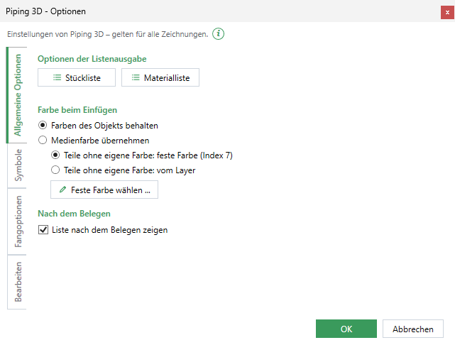
| Settings › Options | General options (list output, color when inserting), symbols (sizes), snap options (radius, connecting), editing (what CAD commands do to the network). |
| Settings › Angle presets | Angles for drawing. |
| Settings › Insulation table | Insulation thickness per system and nominal size. |
| Settings › Pipe settings | Pipe lengths, "With coupling", pipe specs. |
| Settings › Systems | The system definitions. |
| Settings › Levels, System elevations | Reference levels per level; named system elevations. |
| Settings › Drawing units, Snap radius | Units of new parts; size of the snap circle at the cursor. |
| Generate 3D | Ask / do not ask when several are selected. |
| Layers | Create all layers of this plug-in. |
| Levels | Divide across levels, dividing plane, check risers. |
| Help | Online help, Info, "Getting started active", show Getting started. The LuaCAD settings are on the LuaCAD tab › Info. |
Dialog boxes
| Dialog box | Purpose |
|---|---|
| Properties | Change selected pipes, risers and connectors; with several objects only the checked rows. |
| Fitting selection | The catalog has several matching parts – choose one, "reuse" for equal spots. |
| Product | Choose a product from a manufacturer catalog (groups, variants, shape, nominal size, article) or search. |
| Assign symbol | A symbol shown instead of the body – only with the display set to "Symbol". |
| Isometric (options) | Scale, text, dimensions, slope, labels, welds, colors, sheet. |
| Convert 2D | Elevation per system elevation, catalog and pipe spec per system, options. |
| Attributes | Layer and color for annotation, parts and additions. |
| Insulation table | Profiles, steps per nominal size, assigned systems; default profile (*). |
| Options | General, symbols, snap options, editing. |
| Pipe specs | Pipe type, material, pressure rating, temperature, flanges, fittings, bolts, wall per nominal size, specification, branch table (process piping). |
| Spool settings | Spools on, maximum size, numbers. |
| Change welds / weld settings | Process, location, procedure; defaults and size of the weld bodies. |
| Extruded outlet | Which outlet comes out of the clicked pipe. |
Every setting in detail
This section lists every setting of Piping 3D – on the palette, in the gear menu and in the dialog boxes – with its effect, the default value and an example. Values on the palette apply only to parts you insert afterwards; what is already in the drawing keeps its values. Settings in the gear menu apply to all drawings unless "per drawing" is stated. Lengths are typed in drawing units; every field calculates ("600+400" becomes 1000).
Palette, Pipe page
| Setting | What it does | Default | Example |
|---|---|---|---|
| System | Water, heating, gas … for the next pipe – sets color, layer and the insulation from the insulation table. Systems are edited in the gear menu › Systems. The crosshair button next to it picks the system of a pipe in the drawing. | first system in the list | "PWC cold water" for a potable water pipe |
| Catalog | Where pipes and fittings come from: a manufacturer catalog, building services or process piping. The crosshair button picks catalog, product line, nominal size and insulation of a pipe. | default of the system | process piping for a welded pipe |
| Product line / pipe spec | The product line of the manufacturer, or in process piping the pipe spec (pipe type, material, pressure rating). | first product line with press fittings | a pipe spec "CS01" |
| Pipe variant, elbows, tees | Only when the catalog offers several versions: which one assigning uses. Without a choice it takes the first version with a pipe end. Long names are shortened; the full name is in the open list. | first with a pipe end | elbow with spigot end instead of press end |
| DN / Dim | Nominal size and outside diameter of the next pipe (from the catalog). | smallest size | DN 20 / 22 mm |
| Insulation | Insulation thickness in mm; 0 = none. A profile of the insulation table for the system proposes the value. | from the insulation table | 30 mm |
| Insert as | Routing line = only the axis; Generate 3D = assign while drawing; Fitting = a single part (type and part in the lists below). | routing line | draw lines first, then assign all at once |
| Elevation change | Angle of the slope when the elevation changes during a run (90° = vertical). | 90° | 45° for a sloped offset |
| Angle increment | Angle increment while drawing; the Spacebar switches between "snap to angle" and "free". | 45° | 15° for fine directions |
| Property fields of the next pipe | Fields (plant, construction phase …) every new pipe receives. | no values | plant "Building A" |
System elevation (elevation of the next pipe)
| Setting | What it does | Default | Example |
|---|---|---|---|
| Elevation (method) | System elevation = a named elevation (gear menu › System elevations); from level = distance from a reference level of the level; absolute elevation = Z in the drawing; free = the elevation comes from the clicked point. Switching keeps the elevation, only the number is converted. | system elevation | from level, FF, 2400 |
| Level | Only with "from level": the level the distance is measured in (floor-to-floor heights in the gear menu › Levels or on the project palette). | level of the drawing | 1st floor |
| Distance from | The reference level: TOS (top of slab), FF (finished floor), BOS (bottom of slab), FC (finished ceiling); its elevation in brackets. | FF | BOS for a pipe below the ceiling (negative value) |
| System elevation | Only with "system elevation": level and named elevation, distance and reference level in brackets; the height in the level is shown below at Value. If you pick the elevation of a pipe already drawn, its system elevation appears here only if a current system elevation lies exactly at that height – otherwise the absolute elevation. | first entry | "OG1 1st elevation (15 cm from BOS)" |
| Value | The number for the chosen method (distance or absolute elevation). During a run a new number applies only after Enter or the check mark. The crosshair picks an elevation in the drawing. | from the system elevation | 2400 |
| Offset | Only during a run: an elevation offset by this value at the next click. | empty | −300 to pass below a beam |
Palette, other pages
| Page › Setting | What it does | Default |
|---|---|---|
| Risers/Connectors › template list | Which riser or connector template is inserted; "…" opens the templates dialog box. | first template |
| Risers/Connectors › Show the dialog box before inserting | Shows the chosen template for checking before it hangs at the cursor. | – |
| Risers/Connectors › Axis cross in the riser circle | Cross in all rise/drop symbols – per drawing, also for Piping 2D. | – |
| Risers/Connectors › Generate 3D (parallel pipes) | Assign parallel pipes while drawing. | – |
| Symbols › order, search, filter | How the symbol list is sorted (name, recently used …) and what it shows. | – |
| Symbols › Show the definition dialog box when inserting | Ask for designation, article, nominal size and connectors before inserting. | – |
| Custom parts › Folder | Which folder the list comes from; "…" adds folders (also on the network). The examples are in the LuaCAD folder. | examples / first group |
| Products › Show properties before inserting | Open the property fields dialog box before inserting. | off |
| Products › Automatic flange gasket | Insert the gasket together with a loose flange. | on |
| Products › Take over DN | A generic valve takes the nominal size of the pipe it goes into. | on |
| Products › Face-to-face length, Default | Length of the generic valve; "Default" resets the value from the table. | per type and DN |
| Tools › Symbol display | Symbols as 3D bodies, as 2D line drawing or both – whole drawing. | 3D |
| Tools › Product display | Products simple or detailed, as product, symbol 3D or symbol 2D (the assigned symbol). | simple, product |
| Tools › Display of custom parts | Part, symbol 3D or symbol 2D. | part |
| Tools › Insulation | Insulation bodies visible or invisible – whole drawing. | visible |
| Tools › Clashes | Check set (for example "MEP among each other") and settings of the clash detection. | MEP among each other |
| Output › Per network | One list per pipe network instead of one for everything. | – |
| Output › Evaluate visible objects only | Parts on layers that are off or frozen are not counted. | – |
Gear menu › Attributes
Appearance of everything Piping 3D draws besides the pipes. Each button opens the choice of layer, color, linetype and lineweight; "ByLayer" means the layer decides.
| Area | What it controls | Example |
|---|---|---|
| Positioning | Frame, text and leader of the item numbers; "draw" = draw the leader. | text yellow, no leader |
| Lists | Lines, text and title of the tables in the drawing. | title on its own layer |
| Errors | Text of the error labels (for example a pipe that is too short). | red |
| Fittings | Dielectric union between different materials. | red |
| Elevation symbol | Line of the elevation symbols. | black/white |
| Gaskets | Color or layer of the gaskets; "use" = take this value instead of the system's. | gray, use |
| Weld manual / mechanized | Color and size of the weld bodies. | size 1.5 × wall thickness |
| Flange accessories | Flange bolts, collar sleeves; "in the system color", "add sleeves automatically". | bolts in the system color |
| Manufacturer products | Pipes and fittings in the system color; line attributes from the system; per product group (radiators, heat generators, heat pumps) its own appearance. | radiators on their own layer |
| Custom parts | Take the layer from the system or keep the one of the part. | from the system |
Gear menu › Options
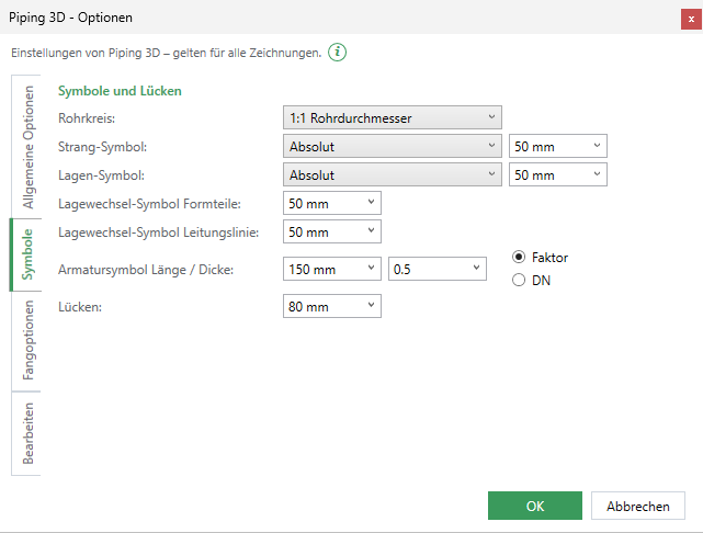
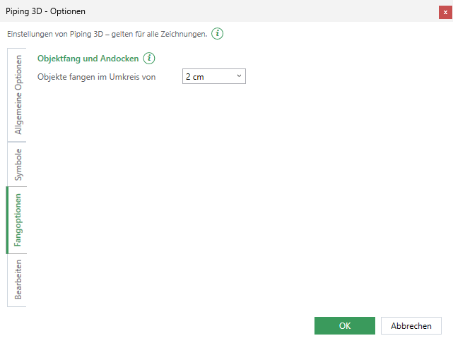
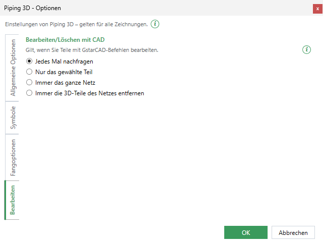
Four tabs; the values apply to all drawings. Lengths are shown in the display unit of the drawing (in a mm drawing the snap distance in cm).
| Tab › Setting | What it does | Default | Example |
|---|---|---|---|
| General options › Options of the list output | Columns, grouping and target of the parts list and the bill of materials. | default template | bill of materials per system |
| General options › Color when inserting | Keep the colors of the object = products, symbols and custom parts keep their colors, only the layer comes from the system; Use the system color = they get the color of the system; parts without their own color then get a fixed color (index 7 = black/white) or ByLayer. | keep colors | system color for a colored riser diagram |
| General options › Show the list after assigning | After "Generate 3D" show the issues list when something does not fit. | on | – |
| Symbols › Pipe circle | Size of the circle of a pipe in plan view: 1:1 pipe diameter, a percentage of it or absolute. | 1:1 | 120 % |
| Symbols › Rise/drop symbol, elevation symbol | Size of the rise/drop and elevation symbols: absolute or a percentage of the pipe or insulation diameter. | absolute 50 mm | 50 % of the insulation diameter |
| Symbols › Elevation change symbol fittings / routing line | Size of the circle where a pipe changes elevation – in the assigned pipe or on the routing line. | 50 mm | 80 mm |
| Symbols › Valve symbol length / thickness | Length of a valve without its own dimensions (total, half per connector) and its thickness as a factor of the length or by DN. | 150 mm, factor 0.5 | thickness by DN |
| Symbols › Gaps | Gap of a lower pipe at a crossing or at a symbol. | 80 mm | 120 mm |
| Snap options › Snap objects within | How close the cursor has to come to a pipe or connector for drawing to connect there. | 2 cm (20 mm) | 50 mm in a dense plan |
| Editing | What Move, Copy and Erase of GstarCAD do to a network: ask, only the selected part, always the whole network or remove the 3D parts. | ask | always the whole network |
Gear menu › Angle settings
| Setting | What it does | Default | Example |
|---|---|---|---|
| Angle offset X-Y / X-Z | How far the angle increment is rotated (plan or vertical); the crosshair picks the angle with two clicks. | 0° | 12° for a skewed building |
| Angle increment X-Y / X-Z | Step of the angle increment while drawing. | 45° | 30° |
Gear menu › Insulation table
| Part | What it does | Example |
|---|---|---|
| Profiles | Named tables; "New" creates one, the trash can deletes. | "heating/hot water (MuKEn)" |
| Up to DN / insulation mm | Per step: up to which nominal size which thickness applies. | up to DN 15 → 40 mm, up to DN 32 → 50 mm |
| Systems | Which systems use this profile (check boxes). | hot water and circulation |
| Default profile | Applies to all systems without their own profile (*). | "cold water 20 mm" |
Gear menu › Pipe settings
| Tab › Setting | What it does | Default | Example |
|---|---|---|---|
| Pipe lengths › catalog, product line, pipe length | Length of the stock lengths per catalog and product line; assigning divides longer pipes into stock lengths. Your own length takes precedence over the manufacturer's. | delivery length of the manufacturer | 6000 mm |
| Pipe lengths › With coupling | Put a coupling between two stock lengths. | on | – |
| Pipe lengths › Open pipe specs … | Edit the pipe specs of process piping. | – | – |
| Bend radius | Radius of bent (flexible) pipes per product line. | from the catalog | 5 × d |
Gear menu › Systems
The system definitions: create systems (Add, Duplicate), rename them and define their appearance per part (Edit: axis, body, insulation, routing line with layer, color, linetype, transparency). "Plug-ins" shows the systems of Piping 3D, Drainage 3D, Ventilation 3D or Piping 2D; "Insert defaults" sets the cost structure. A change set to "ByLayer" goes to the layer in the current drawing.
Gear menu › Levels and system elevations
| Dialog box | What it controls | Example |
|---|---|---|
| Levels | Per level the short name, the designation and the elevations of the reference levels TOS, FF, FC, BOS (absolute, calculating allowed); LuaCAD calculates the floor-to-floor height. "Reference levels …" adds more, "Load from template / Save as template" carries levels between projects. A change never moves an object. | ground floor: FF 0.000, BOS 2.400 |
| System elevations | Named elevations as a distance from a reference level – the elevation results per level. By default four system elevations 15, 30, 45 and 60 cm below BOS. A change never moves a pipe already drawn (see Elevations and reference levels). | "1st elevation" = 15 cm below BOS, shown in lists as "1st elevation (15 cm from BOS)" |
Gear menu › Drawing units, snap radius
| Setting | What it does | Default | Example |
|---|---|---|---|
| Drawing units | In which unit new parts go into the drawing and fields show lengths: automatic (from the drawing), mm, cm, dm, m. Applies to all plug-ins. | automatic | cm for an architect's plan in cm |
| Snap radius when drawing | Diameter of the circle (a sphere in 3D) at the cursor within which a run snaps to pipes. | 30 mm | 60 mm |
Gear menu › Properties, layers, levels, help
| Entry | What it controls |
|---|---|
| Generate 3D › Ask / do not ask when several are selected | Whether "Generate 3D" asks once when several networks are selected. |
| Property fields … | Which fields exist (default fields on/off, your own fields) – for all plug-ins. |
| Property fields of a pipe … | Set the fields of a whole pipe; each of its parts takes them over. |
| Author … | The name in isometric, lists, IFC and clash list. |
| Layers › Create all layers of this plug-in | Creates missing layers; existing ones stay as they are. |
| Levels › Divide across levels settings … | Dividing plane (TOS, BOS, FF, FC), level function on/off, question when drawing across a level boundary (ask, always, never). |
| Levels › Check risers … | Checks the joints of divided risers; the result is shown in the issues list. |
| Help › Getting started active | Cards of the pages and the help before inserting for this plug-in on or off. |