
Basic concepts
Anyone who knows these concepts understands every function of Drainage 3D. The tasks refer here when a concept matters.
Sketch, Generate 3D and fitting by hand
Drainage 3D separates planning from building: you sketch in plan, LuaCAD builds the 3D from it. What the automatic process cannot do, you add by hand.
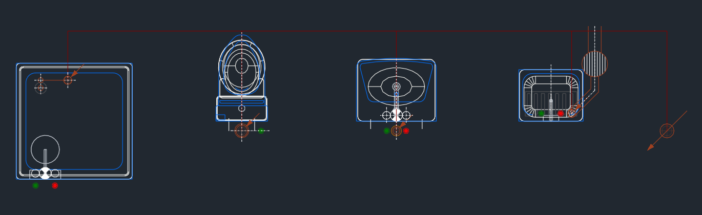
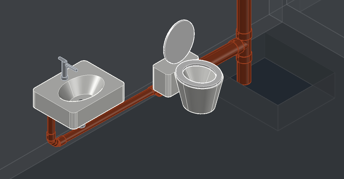
| Sketch (plumbing line and connectors) | Generate 3D | Fitting by hand | |
|---|---|---|---|
| What is created | Connectors (stack, fixture, vent …) and lines in plan, with the values system, level, slope, diameter. | Pipes and fittings sized to the standard, with slope from the stack. | A single fitting or a combination (for example a double 45° bend) from the catalog. |
| When | Always first – fast, easy to change, crossing is allowed. | When the sketch is ready; again after every change. | For vertical parts (stack, double 45° bend, branch offset) and for places you want to define yourself. |
| Changing | Grips, Move, properties of the line or the connector – then generate again. | Never directly: "Generate 3D" replaces the previous parts. | Properties, Shorten, Move; it stays when you run "Generate 3D" again. |
The sketch lies under the 3D
After "Generate 3D" the plumbing lines and connectors lie on a hidden helper layer under the pipes. They carry all values of the network. That is why: you change the sketch, the 3D is generated again.
- Delete 3D removes pipes and fittings – plumbing lines and connectors become visible again.
- Generate 3D on a network that already has 3D replaces the previous parts; fittings placed by hand stay.
- You do not change parts placed by "Generate 3D" one by one with "Properties" – LuaCAD removes them from the selection and says so.
Drainage network
A drainage network is everything connected by lines – from the fixture to the stack the water drains into. Every network gets a number; lists, item numbers and the annotation "All" count per network.
Every drainage network needs:
- exactly one stack down – the water flows there, the slope is built up from it;
- at least one inlet – a fixture or a stack up.
Only objects with the same level and the same system connect to a network. A line that touches no other line and no connector belongs to no network.
Stack down and stack up
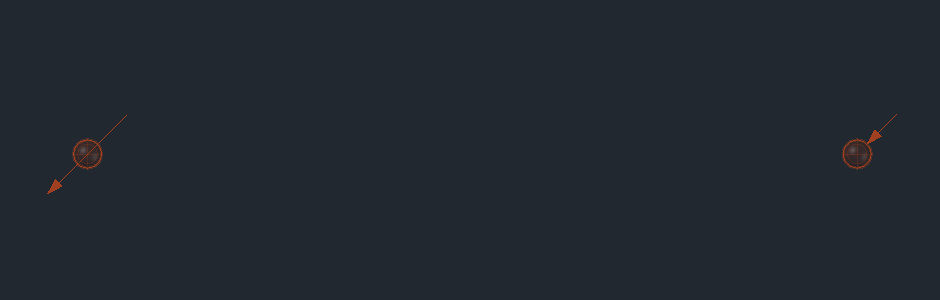
| Stack down | Stack up | |
|---|---|---|
| Meaning | This is where the water leaves the network of this level downward – the start of the drainage network. | Water comes from above into the network (from the levels above). |
| Per network | exactly one | any number |
| Load | – | sum of DU, Qww, continuous flow, storm water or pumped discharge line (dialog box "Load from above") |
| Default elevation | The pipe centerline lies half a diameter below the TOS (top of slab) of the level or below the drawing plane; the slope rises from here. | from the slope of the line |
If a stack reaches across several levels, LuaCAD divides it onto the drawings of the levels – see Stack across levels.
Fixture, vent and connector
A connector is a point where a pipe starts or ends. There are seven types (Connectors page): stack down, stack up, fixture (lavatory, toilet, shower … with its discharge unit DU), vent (no load), offset (a step in elevation in the line) and spot elevation (a fixed elevation on the line). Every connector has fittings: the main fitting directly at the connector and a continuation above or below – "Generate 3D" inserts them too.
A fixture from the Block Library brings its drainage connector; for the calculation the connector is enough.
Standard and sizing
"Generate 3D" sizes the pipes and chooses the fittings according to the standard. It is a preset for all drawings (gear menu › Options › Sizing); the default is DIN EN 12056-2 / DIN 1986-100:
| Standard | What is calculated |
|---|---|
| DIN EN 12056-2 / DIN 1986-100 (Germany, default) | System I: Q = max(K · √ΣDU + continuous and pumped flow, largest DU); collective fixture drains per Table 7, horizontal branches and building drains per Tables A.3–A.5, stacks checked per Table 8. In building drains, horizontal branches and vent pipes only elbows up to 45°, reducers of the building drain flat on bottom, branches up to DN 70 at the stack with a wye 88½°, a stack over 10 m ends at the bottom with a double 45° bend and a 250 mm spacer. |
| SN 592 000 (Switzerland) | For projects in Switzerland: wastewater flow rate Qww = K · √ΣDU, diameters from the tables for fixture drains, stacks, horizontal branches and building drains. |
| no standard – DN by hand | No sizing: all pipes get the diameter you enter on the palette under DN. "Generate 3D" still places fittings and slope (general rules, without the fitting rules of DIN). |
Discharge unit DU and load
- DU (discharge unit, l/s) is the load of a fixture, for example 0.5 for a lavatory, 2.0 for a toilet. It is stored in the template of the fixture.
- ΣDU is the sum of the DU of all fixtures that drain through a section.
- K (frequency factor) describes how simultaneously the fixtures are used: 0.5 house and office (intermittent), 0.7 hospital, school, restaurant, hotel (frequent), 1.0 public toilets and showers (congested), 1.2 laboratory (special).
- Qww (wastewater flow rate, l/s) = K · √ΣDU. From Qww and the slope the standard chooses the diameter.
The result after "Generate 3D" lists ΣDU, Qww, slope and the origin of the diameter for every section.
Slope
The plumbing line is horizontal; the slope is its property. Only "Generate 3D" builds it up: from the stack down every pipe rises toward the fixtures. The slope of new lines is on the palette (default 2 %); in percent or in degrees – switching converts the value. Annotations, lists and notes give the slope in percent, for example "1.5 %".
Drain type
Every plumbing line has a drain type – it decides which table is used for sizing:
| Drain type | What it is |
|---|---|
| Fixture drain | from the fixture to the next pipe |
| Branch drain | collects several fixture drains |
| Horizontal branch / building drain | carries the water to the stack or out of the building |
In addition, Carries says what flows through the line: wastewater, storm water or only air (vent).
Eccentric or concentric reducer
If the diameter changes, "Generate 3D" places a reducer. How the two diameters fit together is chosen on the palette under Reducer:
- eccentric (default): the top of the pipes stays flush (flat on top) – usual for horizontal pipes.
- concentric: the pipe centerline continues.
- At a fixture the reducer is always concentric. Under DIN an eccentric reducer in the building drain lies flat on bottom (DIN 1986-100 6.1.7) – the inverts stay on one line, the water does not back up. If "concentric" is chosen, the choice applies and the result names the DIN rule as a note.
Branch offset
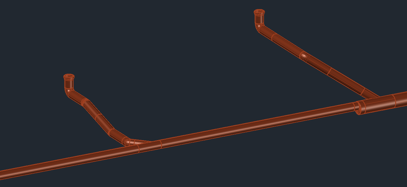
If a fixed inlet (for example a fixture with a fixed elevation) lies higher than the pipe it connects to, the difference in elevation has to be bridged. "Generate 3D" always proceeds in this order:
- First a fitting, the branch offset: below 17 cm difference two catalog elbows (2 × 30° or 2 × 15°, with a pipe in between if needed), from 17 cm a raised wye with an elbow.
- Then more slope: if no fitting fits, the branch pipe falls more steeply – at most 5 %, with an orange note marker.
- Otherwise an error marker with a remedy.
You set all of this in the gear menu › Options › Generate 3D (see Options). On a single connector, "Connect without branch offset" switches it off.
Elevations: top, centerline, invert
A pipe has three elevations: the top, the centerline and the invert – the inside bottom on which the water flows. In drainage the invert usually applies. The elevation of a connector is automatic by default: it results from the slope from the stack. If it has to be fixed at one place (a wall penetration, a tie-in to existing pipes), you set it – from TOS, from BOS (bottom of slab) or absolute, and how strictly: exactly (==), at least (>=) or at most (<=).
The reference levels TOS, FF, FC and BOS of a level are explained under Elevations in LuaCAD.
In-wall carrier
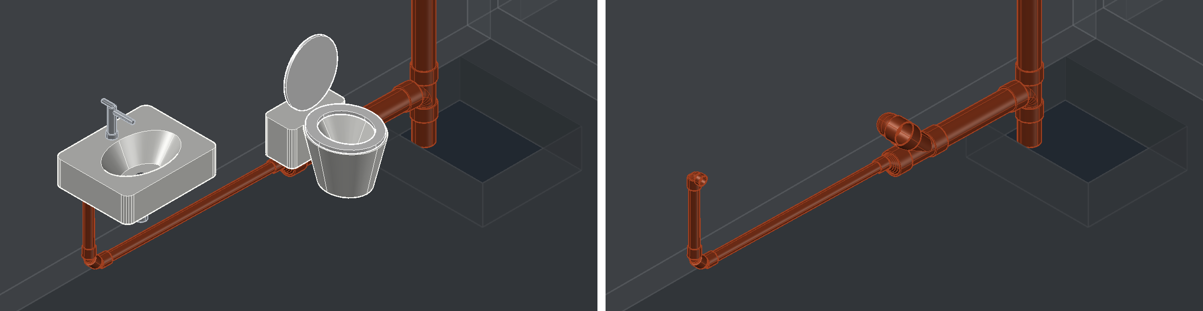
In an in-wall carrier (an installation wall in front of the masonry) fixtures and pipes lie close together. There is a separate method for it, the In-wall carrier routing page: you place the stack and fixtures in plan and draw a line through their connectors – the carrier line. "Generate 3D" calculates the elevations from it: from the centerline elevation of every fixture and the slope of the horizontal branch toward the stack. Networks of the in-wall carrier and of "General routing" are never mixed; you continue with fittings.
Fittings by hand
Everything you place yourself instead of having it generated – a fitting, a combination, a custom part – is a part placed by hand. It connects to a free end or is inserted in-line into a pipe and stays when you run "Generate 3D" again; LuaCAD moves it along where it hangs on a stack or a fixture and reports where this is not possible. If a plumbing line starts at the free end of a chain of parts placed by hand, the pipes connect there.
Lines and CAD commands
Plumbing lines and connectors behave like CAD objects: grips, STRETCH, MOVE, ROTATE, MIRROR, COPY and the Properties palette work. At the end of the command LuaCAD updates the connected lines. What happens to a network that already has 3D (ask, only the selected item, whole network, remove 3D) is set in the gear menu › Options › Editing. A 3D body is never stretched. See CAD commands.
The preview window
The preview window "Drainage 3D - Preview" floats next to the palette and shows, on the page Fittings, the chosen fitting with its catalog bodies in 3D – for a combination all parts together, the way they will be inserted. The header names the name, nominal size, article and the number of parts; if the choice cannot be built this way, it gives the reason.
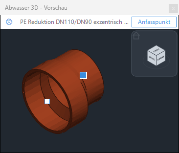
- When it appears: only on the page Fittings, for all three ways – fitting automatic, single and combination. Every change of the choice shows it again a moment later.
- Grips: a click on a grip chooses the base point by which the fitting hangs at the cursor when you insert it; with "fitting automatic" it also switches "At the cursor" in the palette – and the other way round.
- Cube, mouse and gear menu as in every preview window: cube = view direction, drag = rotate, middle button = pan, wheel = zoom; in the gear menu visual style, view, view direction, zoom to fit and Place next to the palette.
- Show and hide: gear menu of the palette › Preview window › Show or Hide. Closed with the cross, it stays closed until you choose Show.
The dialog Branch offset (when generating 3D with the setting "ask") has its own, smaller preview: it shows the solution chosen in the list "Raise by how many degrees?" and rotates and zooms the same way.