
Quick start: the first drainage network
This page shows the shortest way from a bathroom – shower, toilet, lavatory and service sink – to a finished pipe in 3D and the two most frequent changes afterwards. Every step has a picture; the details are in the linked tasks.
1. Open the palette, choose level and system
Ribbon › LuaCAD tab › Drainage 3D. The palette opens at the edge of the drawing on the General routing page.
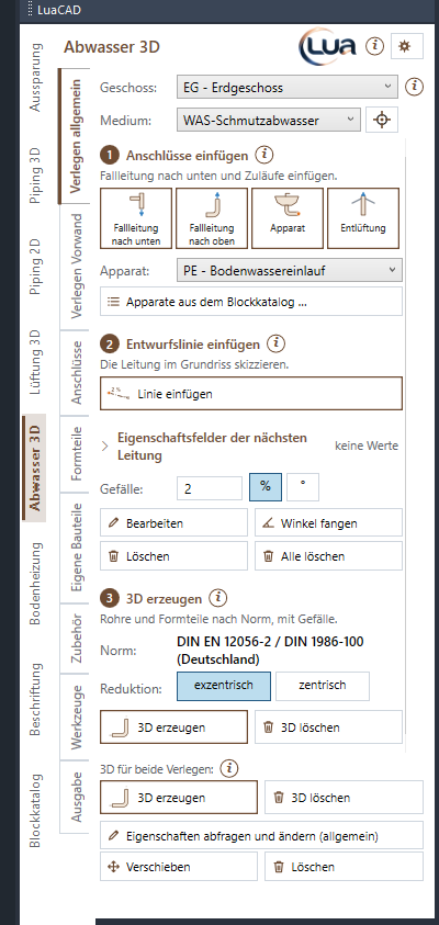
- Level: the level you are drawing in. In a project drawing the level of the drawing is shown here and the list is locked.
- System: for example "wastewater" – it sets layer and color. Lines of different systems or levels never connect.
- Leave everything else as it is for a start: slope 2 %, standard DIN EN 12056-2 / DIN 1986-100 as default (for Switzerland choose SN 592 000 under gear › Options › Sizing).
2. Insert the stack and fixtures
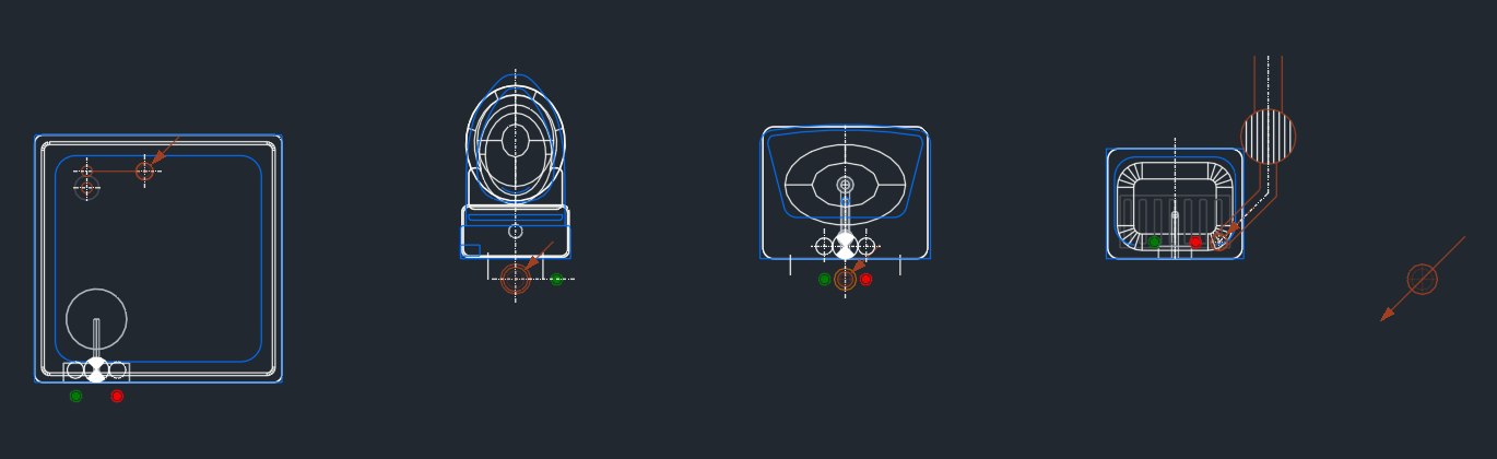
- Insert the fixtures from the Block Library (ribbon › LuaCAD tab › Block Library, folder Fixtures) – in the example a shower tray, a floor-standing toilet, a lavatory and a service sink. Each brings its drainage connector (2–5) with the drainage fixture unit DU of the fixture (toilet 2.0, lavatory 0.5, shower 0.6, service sink 2.5).
- Click the Stack down tile and click the stack at its place (1). This is where the water leaves – the drainage network starts here. Enter ends.
3. Sketch the pipe
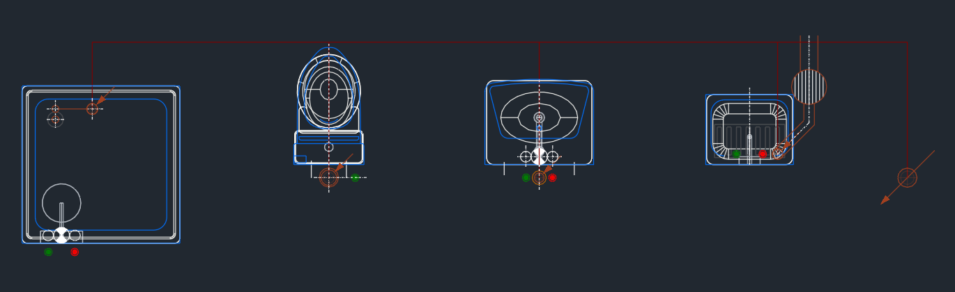
- Click Insert line (step 2).
- Start at the connector of the shower (4) – the line snaps to its connector.
- Click the corners and end at the stack (1) – a click on a connector ends the line there.
- Draw one line each from the toilet, the lavatory and the service sink onto the first line (3). Where lines cross or touch, Generate 3D creates a branch.
The line is only a sketch in plan – it is horizontal; the slope is a property and only takes effect in the next step. More under Inserting a plumbing line.
4. Generate 3D
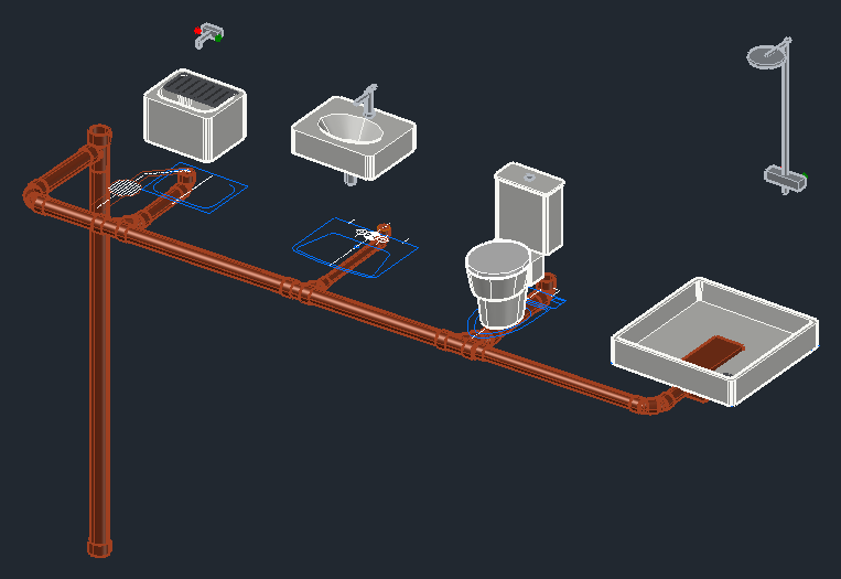
- Click Generate 3D (step 3 or at the bottom in the footer).
- Click the stack – or Enter for all drainage networks of the drawing.
- LuaCAD sizes the pipes to the standard, builds up the slope from the stack and places pipes, elbows, wyes and reducers from the catalog – in the product line of the stack (welded PE or a push-fit system, see Fittings).
The plumbing lines and connectors then lie hidden under the 3D. More under Generate 3D.
5. Read the result
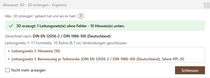
If there is something to say, the result opens afterwards: errors (red, also as a marker in the drawing) and notes (orange). Show shows the place. If LuaCAD suggests a different slope, Apply sets it on the line and generates the 3D of this network again. "Sizing per section" says where each diameter comes from. More under The result.
6. Change: drag a line with its grip
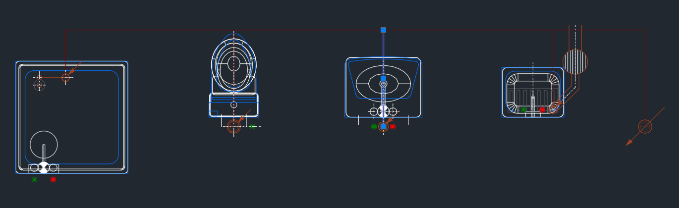
- Click Delete 3D (footer) and click the network: pipes and fittings are removed, plumbing lines and connectors are visible again.
- Click a line – it shows grips at start, middle and end like a CAD line.
- Click a grip, drag it to the new place, click. Connected lines follow.
The CAD commands MOVE, ROTATE and COPY work the same way. More under CAD commands.
7. Change: the slope of a line
- Click Query and edit properties (general) in the footer and click the line; Enter.
- In the dialog box change the slope, for example to 3 %, and click OK.
- Generate 3D – the network is created with the new slope.
More under Editing a plumbing line.
What next?
- An in-wall carrier with toilet and lavatory: In-wall carrier routing.
- Vertical parts by hand – a stack across levels, a double 45° bend: Fittings.
- Annotate diameter and slope, bill of materials: Annotation, Lists.
- Esc cancels any function; another button on the palette cancels the running command and starts the new one. U undoes the last step completely.