
General routing
The process in three steps
The General routing page guides you through what takes most of the work in drainage: the horizontal pipes of a level.
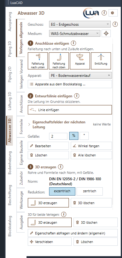
- Insert connectors – the stack down and the inlets (fixtures, stack up, vent).
- Insert plumbing line – the pipe as a line in plan, from connector to connector.
- Generate 3D – pipes and fittings to the standard, with slope from the stack.
For pipes in an in-wall carrier there is the In-wall carrier routing page, for single parts the Fittings page. The concepts are explained in the Basic concepts.
Inserting connectors
Goal: place the points where the drainage network starts and ends – first the stack down, then the fixtures.
- Click one of the four tiles: Stack down, Stack up, Fixture or Vent. For a fixture first choose the template in the Fixture list (lavatory, toilet, shower …).
- The connector hangs at the cursor. Close to the end of a line it snaps there; above a line it drops perpendicular onto it and divides it. With no line nearby it stands free – you draw the line up to it afterwards.
- Click – the connector is placed, the next one hangs at the cursor. With the check box "Show properties before inserting" (Connectors page) the connector dialog box opens after placing.
- Enter = done, Esc = cancel.
Keys at the cursor
| Key | Effect |
|---|---|
| Space | switch the line snap off or on (with a distance: next base point) |
| L | line snap off/on while the Space key switches the base point |
| A | distance to a reference point: amounts X/Y and base point in the dialog box, then click the reference point – see Inserting with a distance |
| E | change the values of the next connectors (for example a fixed elevation) |
Options
- Fixture (list) – the template for the Fixture tile. You maintain templates on the Connectors page.
- Fixtures from the Block Library … – opens the Block Library on the Fixtures page: a complete fixture with 2D, 3D and connectors; its drainage connector comes along.
- All connector types, including offset and spot elevation, and their details are on the Connectors page.
Inserting a plumbing line
Goal: sketch the pipe in plan – roughly, from connector to connector; it is built properly only by "Generate 3D".
- Click Insert line (step 2).
- Start at the connector of a fixture or at the stack – the line snaps to the connector.
- Click the corners. The label at the cursor shows the length and the slope that applies when generating 3D.
- End at a connector or on another line – a click on a connector ends the line there, then the next one starts.
- Enter = line done. Esc = cancel – the segments already placed stay, the piece at the cursor is dropped.
Keys at the cursor
| Key | Effect |
|---|---|
| A | before the first point: distance to a reference point; while drawing: slope, elevation and wall offset in one dialog box (see below) |
| Space | switch between snap to angle (in the angle increment) and free |
| D | type the angle of the increment (degrees) |
| W | pick the angle of the increment with two clicks |
| P | the next click on a plumbing line takes over its system and slope (it does not place a point) |
| N | take over only the system of a clicked plumbing line |
| Arrow key | with a wall offset: switch the side |
Options on the palette
- Slope – the slope of new lines, in % (cm per m) or °; default 2 %. It takes effect only when generating 3D. Switching the unit converts the value.
- Property fields of the next pipe (expandable) – fields every new plumbing line gets, for example a plant or a construction phase.
- Snap radius while drawing – gear menu: the circle at the cursor shows how far the line snaps to lines and connectors (default 30 mm diameter in the drawing).
- Angle increment – gear menu › Angle presets (default 45°).
Slope, elevation and wall offset while drawing
A while drawing opens a dialog box with:
- Slope – applies to the next segment and is taken over on the palette.
- Elevation at the current point – "Now …" shows the elevation. A new elevation applies to the start of the line before the first segment; afterwards a vertical line is created (an elevation change). The crosshair picks an elevation in the drawing.
- Wall offset – the line runs at this distance next to the drawn one; an arrow key switches the side. The wall offset applies only to this run.
- Fixed length – 0 = drag with the mouse; otherwise OK inserts a segment of this length in the current direction.
All fields: Dialog box while drawing.
Rules for a drainage network
- Every network needs exactly one stack down and at least one inlet (fixture or stack up).
- Only lines and connectors with the same level and the same system connect. If a line starts at existing objects in a different system or level, LuaCAD asks by default (gear menu › Options › Generate 3D › "Different system/level").
- If a line starts at the free end of fittings placed by hand, the pipes connect there – see Fittings by hand.
Editing a plumbing line
Goal: change the level, system, slope, diameter or drain type of existing lines.
- Click Edit (step 2) – or Query and edit properties in the footer.
- Click lines or drag a selection window; Enter. Only lines of "General routing" apply here – lines of the in-wall carrier are skipped, the command line says so.
- In the Plumbing line dialog box change the values, OK.
- If the network already has 3D, LuaCAD asks whether it is generated again, deleted or left as it is.
Options in the dialog box: level, system, slope (with unit), diameter ("calculate" = to the standard, a number = fixed), drain type (fixture drain, branch drain, horizontal branch / building drain), Carries (wastewater, storm water, air). After "Generate 3D" ΣDU, Qww and the built diameter are shown below.
Snap to angle
Goal: align the angle increment with an inclined wall.
- Click Snap to angle (step 2).
- Click two points, for example both ends of a wall: their direction becomes the base direction of the angle increment.
- From now on the plumbing line snaps in this direction and in the steps of the increment (default 45°).
You also set the step and the base direction in the gear menu › Angle presets; while drawing, W does the same.
Deleting lines
- Delete (step 2): click lines or drag a selection window – they are removed. Select further lines or Enter = done, Esc = cancel. Every round is one undo step.
- Delete all: all lines of the level and system chosen at the top of the palette – with a confirmation.
You delete connectors and 3D with Delete in the footer.
Generate 3D
Goal: turn connectors and plumbing lines into pipes and fittings – sized to the standard, with slope from the stack.
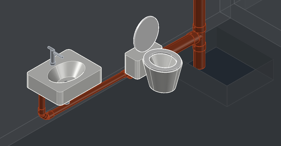
- Click Generate 3D – in step 3, on the In-wall carrier routing page or at the bottom in the footer; it is one button for both routing methods.
- Choose which networks:
- click the stack (or a line, a connector or a pipe of the network),
- click next to the objects and drag a selection window (from the left: what lies completely inside, from the right: what it touches),
- or Enter = all networks of the drawing, general and in-wall carrier.
- LuaCAD sizes, places the parts and shows the progress; Esc cancels and undoes the whole step.
- The command line reports the number of fittings, pipes, errors and notes. If there are errors or notes, the result opens.
What "Generate 3D" does
- It connects the lines at crossings and contacts (wyes), cuts off overhangs and builds up the slope from the stack down.
- It sizes every section from the load (ΣDU, Qww) to the standard – never smaller than the diameter at the connector.
- It places pipes (for fused product lines in stock lengths with a joint), elbows, wyes, reducers and the fittings of the connectors.
- At a 90° change of direction it places a double 45° bend above the set load.
- If a fixed inlet lies higher, it places a branch offset.
- Plumbing lines and connectors go onto a hidden helper layer; item numbers are assigned.
- If the network already has 3D, the previous parts are replaced; fittings placed by hand stay and follow where they hang on a stack or a fixture.
Options
- Standard – the sizing standard is only shown here; it is set in the gear menu › Options › Sizing.
- DN – visible only with "no standard": this diameter applies to all pipes (list of the nominal sizes of the product line, typing also works; default 110).
- Reducer – eccentric or concentric.
- Which fittings "Generate 3D" chooses (double 45° bend, 45° elbows, product line of the network, branch offset, electrofusion couplings) is set in the gear menu › Options › Generate 3D – see Options.
- How long the stock lengths are and how they are joined: gear menu › Stock lengths and welds.
- Connect with electrofusion couplings (gear menu › Options › Generate 3D, default off): with welded product lines (PE, sound-insulated welded) every joint pipe to pipe and pipe to fitting gets an electrofusion coupling instead of butt fusion. Push-fit systems already have their sockets on the fitting.
- Insulation right away: Accessories page, check box "Insulate when generating 3D and inserting".
Standard and diameter
The standard is a preset for all drawings: DIN EN 12056-2 / DIN 1986-100 (Germany) – the default –, SN 592 000 (Switzerland) for projects in Switzerland or no standard – DN by hand. Change it in the gear menu › Options › Sizing. What each one calculates is explained in the Basic concepts. The result shows at the top which one was used. You set the diameter of a single line as fixed in its properties (a diameter instead of "calculate"); at a connector the diameter applies as a minimum.
Eccentric or concentric reducer
eccentric (default): the top of the pipes stays on one line – usual for horizontal pipes; under DIN it lies flat on bottom in the building drain. concentric: the pipe centerline continues. At a fixture the reducer is always concentric. The same setting is in the gear menu › Options › Sizing. Pictures in the Basic concepts.
The result after "Generate 3D"
Goal: see what was built and where problems are – and apply suggestions with one click.
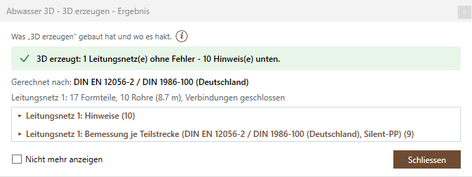
- At the top: the verdict (no errors, or the number of errors) and Calculated to – the standard.
- Below, the figures per network: fittings, pipes with length, joints closed or with gaps.
- The list in groups per network: errors (red, expanded; shown as a red marker in the drawing), notes (orange, collapsed), sizing per section (collapsed) and, if there are gaps, the network check. Clicking a group header expands or collapses it.
- Show (or clicking the row) shows the place in the drawing.
- Apply on a slope suggestion sets this slope as a property of the plumbing line(s) and generates the 3D of this network again; the window then shows the new result.
For every section of the sizing you see the outside diameter (Ø), drain type, ΣDU, Qww, slope (or vertical), the rule of the standard, the number of inlets and the path. All details: Result dialog box.
Delete 3D
Goal: remove the pipes and fittings of a network to change the sketch.
- Click Delete 3D (step 3 or footer).
- Click a pipe or the stack of a network with 3D, drag a selection window, or Enter = all networks (with a confirmation).
- Pipes and fittings are removed; plumbing lines and connectors stay and are visible again.
Then change the sketch and run Generate 3D again. U undoes the deletion.