
In-wall carrier routing
How an in-wall carrier is created
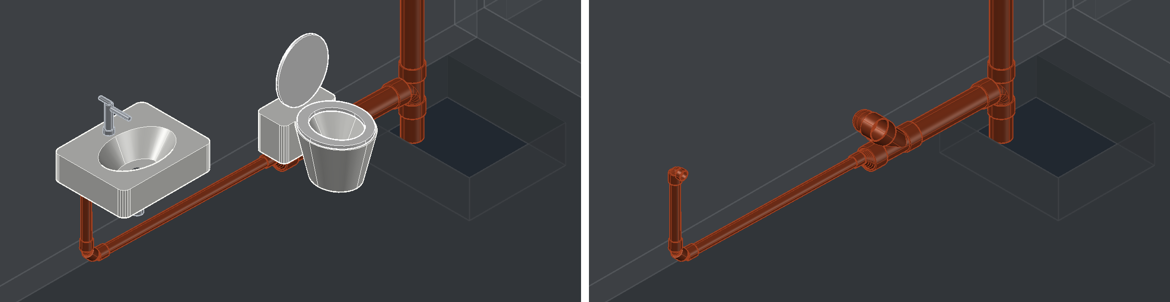
In an in-wall carrier, fixtures, connecting parts and the horizontal branch lie close together. The In-wall carrier routing page builds it from four inputs in plan – "Generate 3D" calculates the elevations.
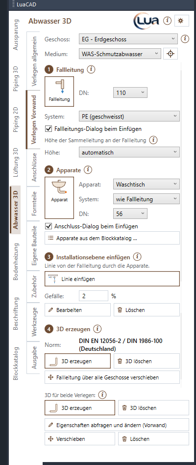
- Insert the stack – it takes the horizontal branch.
- Insert the fixtures – toilet, lavatory, shower … with centerline elevation and connecting parts.
- Draw a line from the stack through the connectors of the fixtures – the carrier line.
- Generate 3D – this creates the stack pipe, the horizontal branch and the connecting parts; the pipe falls toward the stack.
Inserting the stack of the in-wall carrier
Goal: place the stack of the in-wall carrier in plan – across the levels it belongs to one riser.
- Under 1 Stack choose the product line and the DN of the stack pipe.
- Click the Stack tile. If the drawing of another level is loaded as an xref, move the cursor to its stack: the new one snaps there and takes over its name – this is how the levels belong together. Otherwise it snaps to the end of a line of the in-wall carrier or stands free.
- Click. With the check box Stack dialog box when inserting the dialog box then asks for product line, diameter, how the horizontal branch connects and what follows above and below.
- Enter = done, Esc = cancel.
Keys at the cursor
| Key | Effect |
|---|---|
| A | distance to a reference point (amounts X/Y, base point in the dialog box) |
| Space | with a distance: next base point, the distance stays |
The stack dialog box
| Field | What it does | Default |
|---|---|---|
| Level, system | What the stack belongs to. | from the palette |
| Manufacturer, product line | The pipe product line – it applies to stack pipe and horizontal branch of the whole in-wall carrier network (fused or push-fit). A fixture can have a different fused product line. | from the palette |
| Stack pipe | The diameter of the stack pipe (outside diameter, the nominal sizes of the product line). | 110 mm |
| Connector | How the horizontal branch connects to the stack: a wye (88½°, curved wye 88½°, 45°, ball wye …), downward only (double 45° bend, elbow) or straight. | wye 88½° |
| Continuation above | What follows above the top wye: nothing, the pipe up to the top or with a coupling or box at the end. Only selectable with a wye as connector. | pipe |
| Continuation below | What follows below the lowest wye: the pipe into the slab (length below TOS, empty = 250 mm), formwork box, blockout or nothing. | pipe |
| Invert at the connector | The elevation of the horizontal branch at the connector: automatic or fixed (from TOS, from BOS, absolute; ==, >=, <=); the crosshair picks it. | automatic |
Without the check box, the values last chosen apply. The dialog box also opens with Edit on an inserted stack.
Elevation of the horizontal branch at the stack
Under the stack on the palette you find Elevation:
- automatic (default) – the horizontal branch lies as high as all fixtures allow. Usually the best choice.
- fixed, above FF / fixed, above TOS / fixed, absolute – you set the invert at the connector to the stack. What "invert" means there is shown below: at the outlet of the wye, at the 45° elbow, at the double 45° bend or elbow, or at the pipe end – depending on the connector. The crosshair picks the elevation in the drawing (it then applies as absolute).
If the fixed elevation is too low for a fixture or the horizontal branch reaches into the slab, "Generate 3D" says so in the result.
Stack across levels
Only in a project drawing with levels, Stack across levels › To appears under the stack: the level below down to which the stack reaches (default "this level only"). After inserting, LuaCAD asks whether it is divided across the levels – then every level down to there gets a stack of the in-wall carrier in its drawing with the same name and an inlet from above. A level the riser only passes through gets a stack pipe from dividing elevation to dividing elevation when generating 3D. See also Stack across levels.
Inserting a fixture into the in-wall carrier
Goal: place a fixture on the line of the in-wall carrier – the arrow shows on which side it stands.
- Under 2 Fixtures choose in the Fixture list: toilet, lavatory, urinal, bidet, shower, bathtub, sink, washing machine, service sink, back-to-back toilet or back-to-back lavatory.
- Below, the product line ("as stack" or a fused product line of its own) and the DN of the connector – they apply to the next fixtures of this kind.
- Click the Fixture tile. The fixture hangs at the cursor by its connector.
- Move the cursor to the line of the in-wall carrier and click – it sits on the line. With the check box Connector dialog box when inserting the dialog box then asks how it connects.
- The next fixture hangs at the cursor; Enter = done, Esc = cancel.
Keys at the cursor
| Key | Effect |
|---|---|
| R | turn the arrow by 90°: front, left, back, right (also the button "Turn arrow") |
| H | type the centerline elevation |
| A | distance to a reference point, for example a wall corner – on an inclined line X and Y apply along and across the line |
| Space | with a distance: next base point |
The connector dialog box of the fixture
| Field | What it does | Default |
|---|---|---|
| Fixture, short name | Which fixture; the short name appears at the connector in plan and in lists. | per template (WC, WT, UR …) |
| Level, system | What the fixture belongs to. | from the palette |
| Product line | "as stack" or a fused product line of its own – then the connector up to the pipe is made of it. Wye and horizontal branch stay in the product line of the stack. If a part is missing in the chosen product line, the same part is taken from PE (marked "(PE)" in the lists). | as stack |
| Diameter, DU | The connector diameter (nominal sizes of the product line) and the discharge unit DU in l/s (at least 0.05). | per template, e.g. toilet 90 mm / 2.0 |
| Centerline elevation, reference | The elevation of the connector centerline: above FF, above TOS, below FC, below BOS, absolute or free (where you clicked). The crosshair picks it (it then applies as absolute). | per template above FF, e.g. toilet 230, lavatory 550, shower −40 |
| Main fitting | The part at the fixture: coupling with connecting bend (toilet connecting bend), trap connecting elbow, connecting push-fit coupling, toilet connecting coupling (DN 90/100), trap connecting coupling. The coupling always faces the fixture. | per template |
| Continuation behind | Only behind a coupling: elbow 88½°, elbow 88½° long leg, elbow 90°, double 45° bend (vertically down) or elbow 45° (angled down like a toilet). If the pipe comes from behind, the elbow is dropped. | per template |
| Shorten fully | Fused only, in elevation only: shorten the wye outlet, the downward elbow and the toilet connecting bend as far as the catalog allows – the horizontal branch then lies as high as possible. | off |
| Entry | How the connector enters the horizontal branch: Angled 45° (at the end elbow 45°, in the middle wye 45°), Vertical (at the end double 45° bend, in the middle elbow 45° + wye 45°) or Automatic (toilet angled, trap connectors vertical; too low: angled). | Automatic |
| Front view | The sketch shows what the inputs do – at the end of the line and in the middle of the line. | – |
If the fixture comes from the Block Library, Routing appears at the top as well: In-wall carrier (the connector sits at the centerline elevation and is connected with "In-wall carrier routing") or Below ceiling / in the floor (invert at the floor, connected with "General routing"). Switching places the connector again after OK from the template of the other routing.
Back-to-back fitting
The back-to-back toilet and back-to-back lavatory are two fixtures back to back on one fitting. Main fitting and diameter are fixed (the dialog box shows them as a fixed row), the DU applies per fixture. Place this connector only directly on the line – this part has no continuation.
Inserting the carrier line
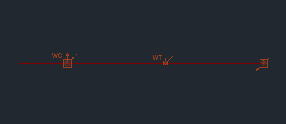
Goal: draw the line along the in-wall carrier to which fixtures and stack attach.
- Under 3 Insert carrier line check the slope of new lines (in %, default 2 %).
- Click Insert line.
- Start at the stack and click the line along the in-wall carrier. Over a fixture the line snaps to its connector and continues to the next. Bends and corners are allowed, also a bend right at the stack (stack next to the wall).
- Enter = done, Esc = cancel – the segments already placed stay.
Keys at the cursor
| Key | Effect |
|---|---|
| A | slope and elevation (no wall offset – the line runs through the connectors) |
| Space | snap to angle / free |
| D / W | type an angle / pick it with two clicks, for example along a wall |
Editing and deleting the in-wall carrier
- Edit (step 3): click lines, fixtures or the stack of the in-wall carrier and change them in the dialog box – only objects of the in-wall carrier. A fixture or the stack opens its dialog box as when inserting, a line opens the Plumbing line dialog box.
- Delete (step 3): click lines, fixtures or stacks and delete them.
- Parts that "Generate 3D" placed in the in-wall carrier can be deleted one by one (without a confirmation) – the neighbors get free connectors, and you place something else there by hand.
Generate 3D in the in-wall carrier
Goal: turn stack, fixtures and line into the stack pipe, the horizontal branch and the connecting parts.
- Click Generate 3D (step 4 or footer) – the same button as on "General routing"; it recognizes from the selection whether a network of the in-wall carrier is meant.
- Click the stack, drag a selection window or Enter = all networks.
- LuaCAD calculates the elevations from the centerline elevations and the slope, sizes to the standard (shown above) and places the parts. What does not work is shown as a red marker in the drawing and in the result.
What happens
- The horizontal branch falls toward the stack; its elevation at the stack comes from "Elevation" (automatic or fixed).
- Every fixture gets its main fitting, the continuation behind and the entry into the pipe.
- If a part is missing in the chosen product line, the same part is taken from PE (with a note); if a spigot end then meets a spigot end in a push-fit product line, a note says that a push-fit coupling belongs in between.
- If a pipe placed by hand runs from above out of another network onto the stack, its load is added as an inlet from above – the upper network needs its 3D for that.
- Generating again replaces the parts; "Delete 3D" leaves the sketch.
- Electrofusion couplings instead of butt fusion: gear menu › Options › Generate 3D › "In-wall carrier routing: connect with electrofusion couplings" (default off, fused product lines only).
Moving a stack across all levels
Goal: move a stack of the in-wall carrier – the stacks of the same name on the other levels and the lines on it go along.
- Click Move stack across all levels (step 4).
- Click the stack and click the new position.
- LuaCAD asks whether the stacks of the same name on the other levels go along; the attached lines follow.
The same happens when you move the stack with the CAD command MOVE.