
Accessories
Electrofusion couplings, pipe clamps, wall flanges and insulation sit on the pipes. If you generate the 3D again, they move onto the new pipes. You insert manholes and trench drains freely.
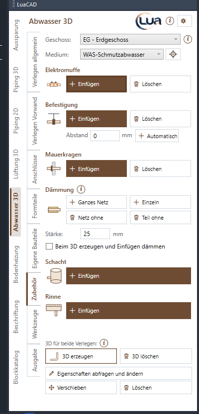
Electrofusion coupling
Goal: join two pipes with an electrofusion coupling instead of butt fusion – fused product lines only.
- Click Insert under Electrofusion coupling.
- Click a pipe at the desired place – the coupling divides it there. Or click a free connector – the coupling goes onto it.
- Click further places or Enter = done.
Delete under Electrofusion coupling: click an electrofusion coupling – it is removed, the two pipes become one again.
Supports (pipe clamps)
Goal: place pipe clamps on a pipe – one by one or evenly distributed.
- Click Insert under Supports.
- Click a pipe and slide the clamp along – every click inserts one.
- Enter = click another pipe; Enter again = done.
Automatic: select pipes (click or selection window) – they get evenly distributed clamps; previous clamps of these pipes are replaced.
Options
- Spacing – the largest clamp spacing for "Automatic" in drawing units. 0 (default) = per manufacturer data: horizontal 10 × outside diameter, vertical 15 × outside diameter.
Delete under Supports: click clamps and delete them.
Wall flange
Goal: place a wall flange at a wall penetration.
- Click Insert under Wall flange.
- Click a pipe and slide the wall flange to the wall penetration – every click inserts one.
- Enter = done. Delete: click wall flanges and delete them.
Insulation
Goal: insulate pipes and fittings – a whole network or single parts.
| Button | Effect |
|---|---|
| Whole network | Click a part – the whole drainage network gets insulation. |
| Single | Click parts or drag a selection window – they get insulation. |
| Network without | Click a part – the whole drainage network loses its insulation. |
| Part without | Select parts – they lose their insulation. |
Options
- Thickness – the insulation thickness in mm for "Whole network" and "Single"; default 25 mm.
- Insulate when generating 3D and inserting – new pipes and fittings get the insulation right away; default off.
Color and transparency of the insulation: gear menu › Systems (position "Insulation", default 80 % transparent by layer) or gear menu › Attributes.
Manhole
Goal: insert an inspection chamber, pump sump, silt trap or oil separator freely.
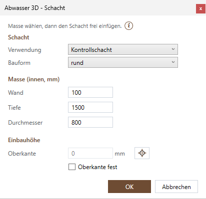
- Click Insert under Manhole.
- In the dialog box choose use and shape – only the matching dimensions (measured inside) appear, plus the top edge.
- OK – the manhole hangs at the cursor by its top edge; every click inserts one.
- Enter = done; Esc returns to the dialog box.
System and level come from the palette. The values are kept for the next manhole. Every field: Manhole dialog box.
Trench drain
Goal: insert a trench drain (always rectangular) freely.
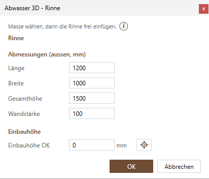
- Click Insert under Trench drain.
- In the dialog box enter the outside dimensions (length, width, total height), the wall thickness and the installation elevation of the top – the crosshair picks the elevation in the drawing.
- OK – the trench drain hangs at the cursor; every click inserts one. Enter = done, Esc = back to the dialog box.
Every field: Trench drain dialog box.