
Concepts
Anyone who knows these concepts understands every function of the Openings plug-in. The tasks refer here when a concept matters. General concepts of all plug-ins (palette, layer, level, elevations, drawing units) are explained in Getting started › Concepts.
The opening
An opening is the place where a building element must stay open or be opened for building services: an opening through a wall or slab, a chase, a sleeve, a core hole. In LuaCAD it is a block in the drawing carrying its data: form (box or cylinder), type, dimensions, clearance, disciplines, description and sequence number. The data are what counts – whatever you change with the CAD (move, rotate, grips), LuaCAD carries over into the data at the end of the command.
An opening exists in two versions: as a 2D symbol for the plan and as a 3D solid for the model, the clash check and IFC – see 2D, 3D and the fixed pair.
Box and cylinder
| Box | Cylinder | |
|---|---|---|
| Types | openings, chases, furring wall | sleeves, core holes |
| Dimensions | Width X, Depth Y, Height Z | Radius and Length (wall) or Height (slab, floor, foundation) |
| Orientation of the solid | edges parallel to X, Y, Z; rotated only about the vertical axis | in a wall the axis is horizontal, in slab, floor and foundation vertical |
| In the plan (2D) | rectangular outline | vertical: circle; in the wall: rectangular outline (diameter × length) |
| Size in schedule and annotation | wall: width × height; slab, floor, foundation: width × depth | Ø diameter |
The template decides whether it is a box or a cylinder. A cylinder starts at the cursor rotated by 90°.
The types
The type says what the opening is. It determines the abbreviation, the symbol in the plan, the look (display by type), the order in legend and numbering and the proposed dimensions when a template leaves dimensions open.
| Type | Form | Abbreviation | Symbol in the plan (default) | Proposal for open dimensions |
|---|---|---|---|---|
| Wall opening | box | WD | diagonal | 300 × 200 × 300 |
| Slab opening | box | DD | cross (both diagonals) | 400 × 400 × 250 |
| Floor opening | box | BD | cross | 400 × 400 × 250 |
| Foundation opening | box | FD | cross | 400 × 400 × 600 |
| Wall chase | box | WS | angle bottom right | 150 × 100 × 1000 |
| Slab chase | box | DS | angle top left | 1000 × 150 × 100 |
| Floor chase | box | BS | angle top left | 1000 × 150 × 100 |
| Slab opening with wall chase | box | DD/WS | diagonal with angles, without hatch | 400 × 400 × 250 |
| Furring wall | box | VM | angle top left | 1200 × 200 × 1200 |
| Wall sleeve | cylinder | WFR | axis, hatched | R 60, L 200 |
| Slab sleeve | cylinder | DFR | axis cross, hatched | R 60, H 250 |
| Floor sleeve | cylinder | BFR | axis cross, hatched | R 60, H 250 |
| Foundation sleeve | cylinder | FFR | axis cross, hatched | R 60, H 600 |
| Wall core hole | cylinder | WBL | axis | R 60, L 200 |
| Slab core hole | cylinder | DBL | axis cross | R 60, H 250 |
Dimensions in mm (width × depth × height). Boxes are hatched by default (except slab opening with wall chase). Every template and every single 2D opening can have a different abbreviation, symbol and hatch.
2D, 3D and the fixed pair
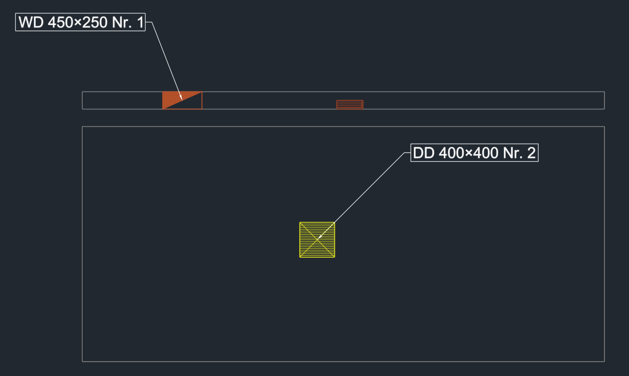
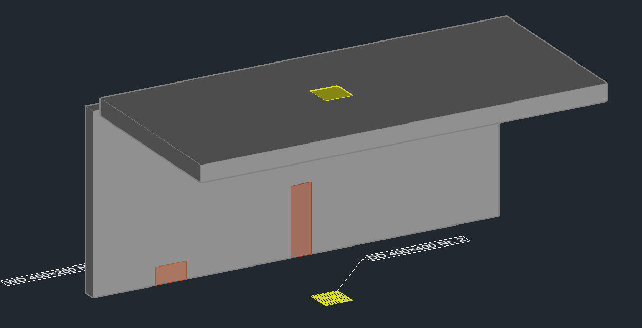
| 2D | 3D | 2D and 3D (pair) | |
|---|---|---|---|
| What is created | outline with hatch and symbol at elevation 0 | a solid (box or cylinder) | both, linked |
| What for | the printed plan | model, clash check, IFC | plan and model |
| Elevation | none | from the clicked point or fixed (key A) | the solid with its bottom at elevation 0 |
| In schedule and legend | one row | one row | one row (at the 2D), the 3D supplies bottom and top |
| Number | its own | its own | the same for both |
A pair is created when inserting with "2D and 3D" or with 2D → 3D …. It always belongs together:
- 2D moved, rotated or changed in its dimensions → the 3D follows in plan, its elevation stays.
- 3D moved, rotated or changed in its dimensions → the 2D follows. Only the elevation of the 3D changed → the 2D stays.
- One side deleted (palette or ERASE) → both are gone; U brings both back.
- A copy is never linked – it gets a new identifier and a new number.
Clearance
The dimensions of an opening are the net dimensions – for example the pipe with insulation. The clearance is the space added (room for installation, insulation, firestopping). It applies per side and only to the dimensions where with clearance is checked:
- Width, depth, height, length: twice the clearance added (both sides). Width 200, clearance 50 → 300.
- Radius: the clearance once – the diameter thus grows by twice the clearance.
The opening is drawn, listed, annotated and written to IFC with clearance. The dialog box always shows the net dimensions – so the clearance is not added twice when you change it a second time.
Base point
The base point is the point by which the opening hangs at the cursor – and with which you place it on the wall edge, in a corner or on an axis. There are points on the outline without clearance (the net dimensions) and with clearance (the drawn opening):
- 2D: nine points on the net dimensions (corners "top left corner" …, edge midpoints "top edge" …, "center"); if a clearance acts in plan, eight more on the outline with clearance ("top left with clearance" …). Without a choice the 2D hangs by the bottom left corner without clearance.
- 3D: the corners (with and without clearance), the edge midpoints at the top and bottom, the face centers (for slab, floor and foundation at the top and bottom, for walls at the sides). Without a choice the solid hangs by its center.
- You choose it in the palette with Base point: choose in the preview or at the cursor with the Space; it is remembered per type and per 2D/3D. When changing, the same point is called Fixed point – it stays put when the dimensions change.
See Choosing the base point and Fixed point.
Template
A template is an opening without a location that fills in the dialog box when inserting: name, form, type, dimensions, clearance and which dimensions get it, disciplines, the lists of descriptions and the display in the plan (abbreviation, symbol, hatch). The order of the templates in the gear menu › Manage templates … is the order of the list in the palette. A template may leave dimensions open (0) – then the dialog box proposes the dimensions of the type. See Managing templates.
Display by type
How an opening looks in the drawing is set by its type: layer, color, linetype, lineweight and – in the plan – the hatch (lines, solid fill or a pattern). In addition, the symbol and the hatch of the 2D can have their own look for all types, for example the hatch on its own layer. Whatever is not chosen comes from the layer. Set in the gear menu › Display by type …; the look applies to new openings, the hatch also to the 2D openings already in the drawing. See Display by type.
Sequence number
Every opening gets the next free number of the drawing when it is inserted; a 2D/3D pair shares it. It is a property field ("Number"): you can change it in the Properties palette, the partner follows. A copy gets a new number. Renumber … assigns 1, 2, 3 … by type, then from top to bottom and from left to right. See Sequence number.
Disciplines, description and property fields
- Disciplines (Plumbing, Heating, Cooling, Ventilation, Electrical, plus "Other" as free text): who needs the opening. Schedule and legend sort by them; without a discipline it says "no discipline".
- Description and Additional description: free texts, chosen from the lists of the template or typed. Without a description LuaCAD proposes the type.
- Property fields of the opening: by default Number, Approval (requested, approved, completed) and Firestop rating (–, EI 30, EI 60, EI 90). Fields with "ask before inserting" appear in the palette under Property fields of the next opening. Which fields exist is set in the gear menu › Property fields …. An opening has no article number and no manufacturer.
Openings and CAD commands
Openings follow the commands of GstarCAD: MOVE, ROTATE, MIRROR, COPY, ERASE, grips and the Properties palette. At the end of the command LuaCAD creates the opening again at its new location and updates the partner – in the same undo step.
- 2D openings have grips at the corners and edge midpoints (outside with, inside without clearance) and can be changed in width and depth with STRETCH.
- 3D solids are never stretched or scaled: after STRETCH, SCALE or a scale in the palette they jump back – "Change dimensions with "Change properties"."
- A tilted solid keeps only the rotation about the vertical axis.
Layers
Without your own choice the openings are on their own layers, which LuaCAD creates by itself:
| Layer | What for |
|---|---|
LuaCAD_BAU_Aussparung | 3D openings |
LuaCAD_BAU_Aussparung_2D | 2D openings (outline, symbol, hatch) |
LuaCAD_BAU_Beschriftung Aussparung | annotations of the openings |
You change name, color, linetype, plotting and on/off in the Layer Manager of GstarCAD – the assignment stays, new openings go to the renamed layer. A different layer per type is chosen under display by type. Gear menu › Layers › Create all layers of this plug-in creates them all at once. See also Layers.
The preview window
Openings have no floating preview window: their preview is in the dialog box "Openings - Choose base point" (palette › "Base point: choose in the preview"). It shows the opening of the form from above with all possible base points as markers – with an allowance inside at the rough size and outside at the outline.
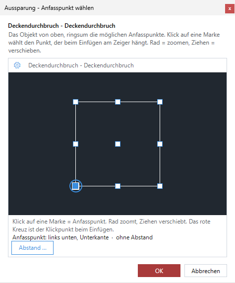
- Use: a click on a marker chooses the point that hangs at the cursor when you insert; the wheel zooms, dragging pans. The view stays from above – nothing can be rotated here.
- Distance … adds a distance X/Y from the base point (valid for this session).
- OK keeps the choice, Cancel leaves point and distance as before. At the cursor Space keeps cycling through the base points.