
Concepts
Whoever knows these terms understands every function of the Block Library. The tasks refer here when a term matters. General terms of all plug-ins (palette, system, layer, level, drawing units) are explained in Getting started › Concepts.
Block and fixture
Every DWG (or DXF) of a library is a block: when inserted it is loaded once into the drawing as a block definition (name = file name, insertion point = base point of the DWG), each insertion is a block reference. A fixture is a block with connectors for the plug-ins.
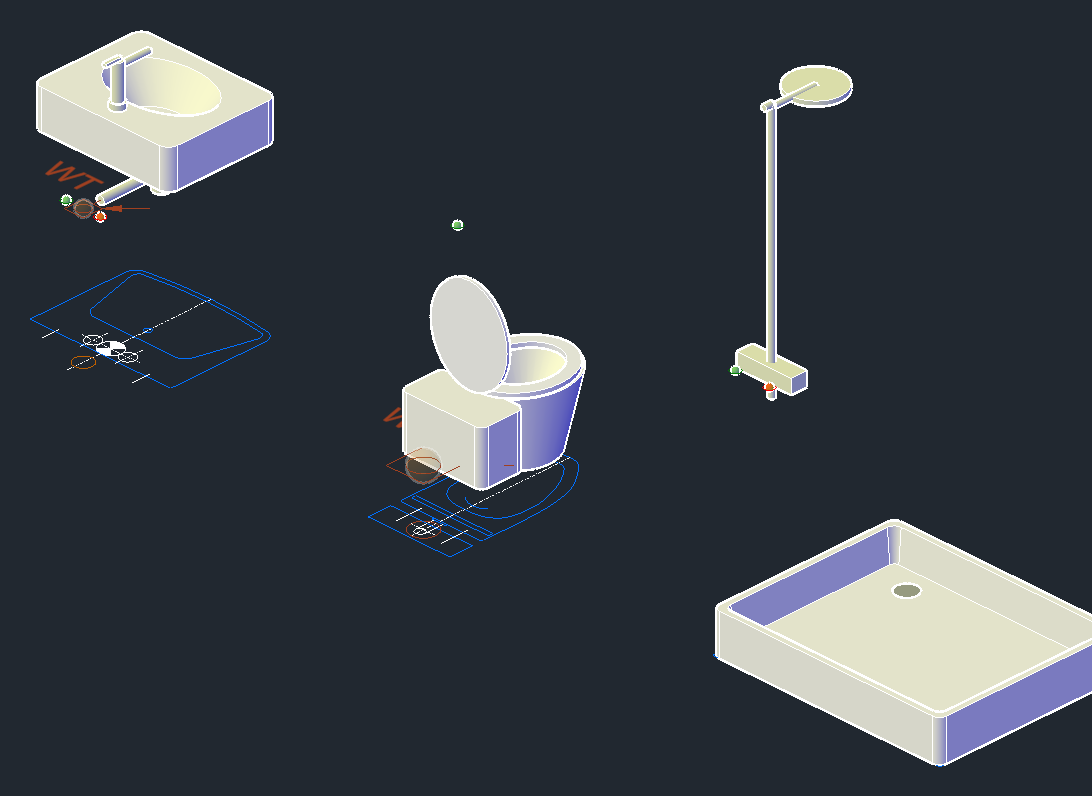
| Block | Fixture | |
|---|---|---|
| What it brings | geometry (2D, 3D or both) and properties | plus connectors: cold water, hot water (some also recirculation, heating, gas) and a drain |
| How it is recognized | – | type "fixture" in the DWG (the block wizard writes it); the Fixtures page lists the blocks from folders named Apparate |
| What the plug-ins do | nothing – it is a drawing part | Piping 3D and Piping 2D connect to the water connectors, Drainage 3D to the drain |
| Extra in the palette | – | connector set, drainage routing, "insert connectors only" |
The connectors belong to the fixture: they move along when moving, rotating, copying and deleting; a copy gets its own.
Standard blocks and custom blocks
| Standard blocks | Custom blocks | |
|---|---|---|
| Where they are | in the program folder (<GstarCAD>\LuaCAD\Bloecke), supplied | in folders you add (gear menu › Folders …); by default the folder "Custom blocks" under AppData\Roaming\LuaCAD\Bibliothek\Bloecke, network drives too |
| In the folder tree | always at the top | below, in the order of your list |
| Changing | never – read-only (no new folder, no renaming) | freely: create, rename, delete folders; the block wizard saves here |
| Layers | the insertion goes on the layer of its group (for example LuaCAD_SAN_Apparate), the content is on layer 0 | the insertion is on layer 0, the content keeps the layers, colors and linetypes of its DWG |
| Defaults from palette and settings | standard fixtures accept the drainage routing and the systems of fixture connectors | a custom fixture keeps its connectors exactly as they are defined in the block |
The standard blocks are sorted by discipline: fixtures (the standard fixtures with connectors), architecture, fire protection, electrical, heating, ventilation, title blocks and layouts, plumbing. Folders whose name starts with "_" or "." (such as _Bilder) are not shown – they hold preview images and helper files.
2D, 3D and "connectors only"
The switch at the top of the palette and the check box at the bottom give four cases together:
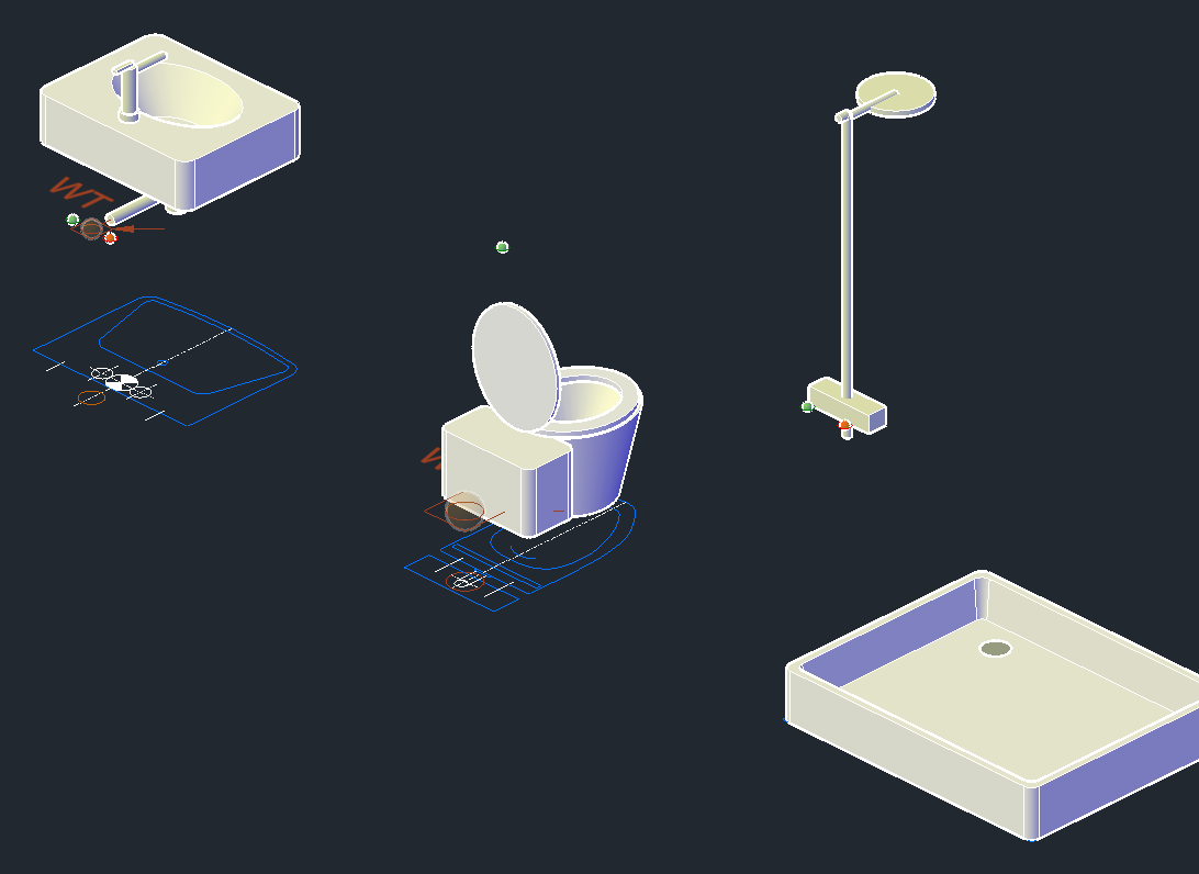
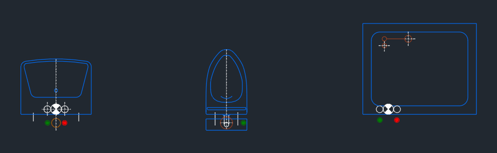
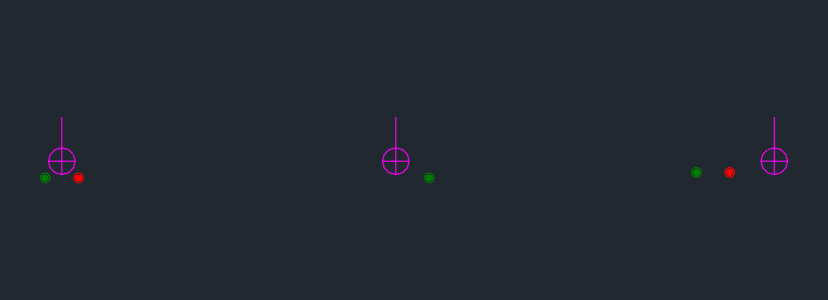
| 3D | 2D | connectors only (check box) | |
|---|---|---|---|
| What you see in the palette | blocks with solids | blocks with 2D parts (floor plan, symbol, title block) | as the switch |
| What is inserted | the block with solid, at the elevation from the palette | only the 2D parts, in the drawing plane (elevation 0) | instead of the fixture only its connectors with a small marker – in 3D at their elevation, in 2D as marks |
| Connectors of a fixture | connector objects for Piping 3D and Drainage 3D | colored marks in the color of their system, for Piping 2D | as on the left, without the fixture |
| Elevation, drainage routing | yes | not used | yes in 3D |
| What for | design in 3D | floor plans, Piping 2D | the architect has already drawn the fixture |
A block that has both (solid and floor plan) appears in both modes. A block without solids is a 2D block and appears only under 2D; a block made only of solids only under 3D. The "connectors only" check box applies only to fixtures – other blocks always come complete. To switch a placed one: Properties palette › LuaCAD › Display (fixture | connectors only).
Connector set
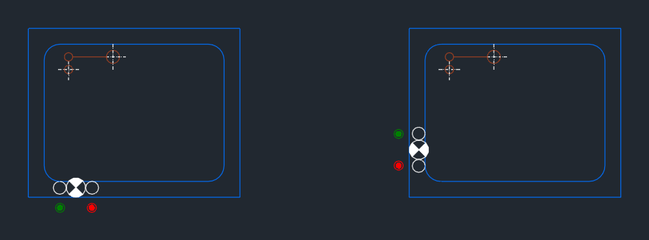
Some fixtures have several connector sets – for example a shower with the valve on the back wall (A) or on the side wall (B), a bathtub with the valve on the long wall (A) or on the end wall (B). Which one applies is the connector set. You choose it before inserting in the palette under Connectors (the row appears only for such fixtures, the choice is remembered per fixture) and change it later in the Properties palette or the shortcut menu; connected pipes follow. A is the default set.
Insertion point and base point
- The insertion point is the base point of the DWG. For standard fixtures it is at the wall, in the middle, on the floor; in the DWG the front faces +Y (into the room).
- The base point is the point by which the block hangs at the cursor: by default the insertion point, with the Space a corner, a midpoint or a connector, with G any point on the block. The corners are "left back (wall)", "right back (wall)", "right front", "left front", plus "middle back (wall)", "middle front" and "middle".
- Chosen in the preview window, a base point applies the next time this block is inserted; a connector clicked there hangs at the cursor.
Elevation
In 3D every block goes to the elevation from the palette: absolute elevation (the Z coordinate), from level (level, reference level TOS, BOS, FF or FC and a value) or free (the elevation of the clicked point; object snap takes the elevation of a part). The elevation means the insertion point – for a standard fixture the floor; the fixture brings its own connector elevations. The reference levels are explained in Elevations and reference levels. In 2D there is no elevation.
Properties of a block
A placed block carries two kinds of values:
| Property fields | Dimensions | |
|---|---|---|
| What | article number, description, manufacturer, type, room … and your office's own fields | width, depth, height, weight; on fixtures also distance CW–HW, water connector elevation, water DN and display |
| From where | the defaults of the DWG, overridden by "Properties of the next block" | from the DWG or from the position of the connectors |
| Where to change | Properties palette (category of the property fields), Current Drawing page | Properties palette › LuaCAD – a new width, depth or height scales the block, a new distance CW–HW moves the connectors |
| Which exist | gear menu › Property fields … (for all plug-ins) | fixed |
Both appear in the block extract, in lists, in annotation and in IFC. Attributes that a third-party DWG brings stay attributes of the block.
Layers
- Standard blocks: the insertion is on the layer of its group – plumbing fixtures on
LuaCAD_SAN_Apparate(in 2DLuaCAD_SAN_Apparate_2D), light fixtures onLuaCAD_ELT_Leuchtenand so on; the content is on layer 0 and brings its colors. LuaCAD creates these layers itself. Change names, colors, plotting and on/off in the GstarCAD Layer Manager – the assignment stays. - Custom blocks: no LuaCAD layer. The content keeps the layers of its DWG (missing ones come along, layers of the same name in the drawing stay as they are), the insertion is on layer 0.
- Connectors only: on the layer of the plumbing connectors.
Gear menu › Layers › Create all layers of this plug-in creates the layers of the standard blocks at once. See also Layer.
Mirroring: cold water stays on the right
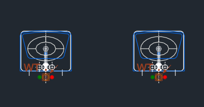
A fixture can be mirrored – at the cursor with M or placed with MIRROR of GstarCAD. Shape and drain are mirrored; the water connectors follow the plumbing rule cold water right, hot water left (seen from the front) – they swap places for it. The command line says so after the first mirrored fixture.
Blocks and CAD commands
Blocks of the library behave like other block references: grips, MOVE, ROTATE, MIRROR, COPY and ERASE work, the connectors move along (in the same undo step).
- A 3D block is never scaled: after SCALE or a scale in the palette it springs back – "Change the size with width, depth and height in the properties".
- If a block is on a locked layer, LuaCAD changes nothing and says so.
Scale factor of a folder
A folder of the library can carry a scale factor: blocks from it go into the drawing at this scale (for example 50 for plan symbols that would be too small at 1:1). It applies to the folder and its subfolders as long as one has no factor of its own, and appears in the tree after the name ("×50"). Fixtures with connectors always keep their size – their dimensions are real millimeters. The factor is stored only in your settings, never in the folder – so it works for the standard blocks too.
The preview window
The preview window "Block Library - Preview" floats next to the palette and shows the block whose tile you clicked last – with the switch on 3D with its body and connectors, on 2D only its 2D parts from above. The DWG is only read for this; the drawing stays untouched.
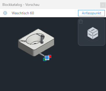
- When it appears: when you click a tile (a double-click inserts the block right away).
- Markers: the connectors in the color of their system; for a fixture with several connector sets those of the set chosen in the palette. A click on a marker sets the point by which the block hangs at the cursor the next time you insert it.
- Header, cube and mouse: the gear on the left (visual style, view, rotate, view direction, show dimensions, choose base point, zoom to fit, place next to the palette), Base point on the right; the cube chooses the view direction, dragging rotates, the middle button pans, the wheel zooms.
- Show and hide: gear menu of the palette › Preview window › Show (shows the last chosen block again) or Hide. Closed with the cross, it stays closed until you choose Show.