
Leaders
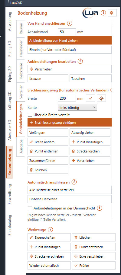
Leaders carry supply and return from the manifold outlet to the loop – always as a pair at the center-to-center distance. The page is ordered from top to bottom: connect by hand, edit, leader corridor, connect automatically.
Draw leader by hand
Goal: draw supply and return of a loop yourself from the outlet to the loop – corner by corner.
Steps
- At the top enter the center-to-center distance – the distance between supply and return, center to center (default 50 mm, allowed 20 to 300 mm). It also applies to automatic connecting.
- Click Draw leader by hand. Before the first click the insertion help shows the procedure with a picture.
- 1 of 2: click the manifold at the outlet – supply and return hang at the cursor right away. (Or click the loop; if it has no manifold yet, the command line asks for it. If the outlet is still free, you choose the loop to connect there.)
- 2 of 2: click the corners. By default the pipes run in 90° increments, aligned with the manifold.
- Arriving: a click on the loop (heated area, heating pipe or the cross at the connector) connects – so does F at any time. A click into another heated area connects to its loop; that loop gets the outlet where the run started. The bar at the cursor names the loop ("connect to loop 1.03").
- Enter or Esc before the loop = stop here: the pipes get an open end. The command line gives length and "connected to the loop" or "open end" for each pipe.
Keys at the cursor
| Key | Effect |
|---|---|
| Space | angle in turn: 90° → 45° → free |
| V | spacing increment on/off: the length of every segment is rounded to multiples (default 100 mm) |
| A | "Spacing increment / wall offset": the value of the increment and a wall offset for this run |
| ← / → | with wall offset: switch the side of the wall |
| S | the pair to the other side of the drawn line |
| F | connect to the loop now |
| I | continue with supply or return only – the other pipe ends here |
| W | pick the base direction of the increment (two clicks) |
| D | type the base direction |
| Enter / Esc | stop here – placed segments stay |
Options
If the loop is already connected, the plug-in asks: Redraw by hand (the pair is drawn anew and stays as drawn) or Recalculate as bundle (the loop runs in the bundle of the manifold again, updated automatically).
Single (supply or return only)
Goal: draw only one of the two pipes – for example to continue at an open end.
Steps
- Click Single (supply or return only).
- 1 of 2: click supply or return – a leader (at the open end it continues), an occupied outlet on the manifold, or a heating pipe of the loop.
- 2 of 2: click the corners up to the cross at the loop; a click on the loop or F connects. Enter or Esc = stop here.
The other pipe stays as it is. In a running run by hand, I does the same.
Edit with grips
Goal: adjust a leader with the GstarCAD grips.
- Click the leader – the grips appear.
- Drag the midpoint grip of a straight segment: the whole segment moves sideways, the bends next to it keep the bend radius. Drag a corner: the corner moves, the segments next to it follow.
- Hover over a corner grip: in the GstarCAD menu Remove vertex takes the corner away (at the loop the pipe gets shorter and an open end), Add vertex makes a new corner.
The partner (supply or return) follows at the measured distance where that is unambiguous; otherwise the command line says so. Afterwards the leader is by hand. Automatic again in the tools recalculates it in the bundle.
Move
Goal: move one or more straight segments of leaders sideways.
Steps
- Click Move. Before the first click the insertion help shows the procedure.
- Click straight segments (they stay highlighted, clicking again deselects) – or click next to the pipes and drag a window. The bar at the cursor offers "Select / deselect segment", "Drag window" and "Finish – move".
- Enter or Finish – move.
- Click the new position – or press A and type a distance. Supply and return move together.
Every segment is moved as with the midpoint grip, also the first and the last one: the end stays at the manifold or the loop, and two corners are added. Only segments parallel to the first one are moved. The moved leaders are by hand afterwards.
Cross and swap
Goal: let supply and return change sides at one end – or swap their tracks.
Steps
- Click Cross or Swap. Before the first click the insertion help shows the procedure.
- Cross: click a leader – at the end nearest to the click supply and return cross: near the loop just before the loop (1), near the manifold right in front of the cabinet (2). Again at the same end = crossing removed.
- Swap: click a leader – supply and return swap tracks, the loop stays. Because outlets and ends stay, they cross at the ends for that. Again = back.
- One step per click; the command line says where they cross now. Enter = finish, Esc = cancel.
Insert leader corridor
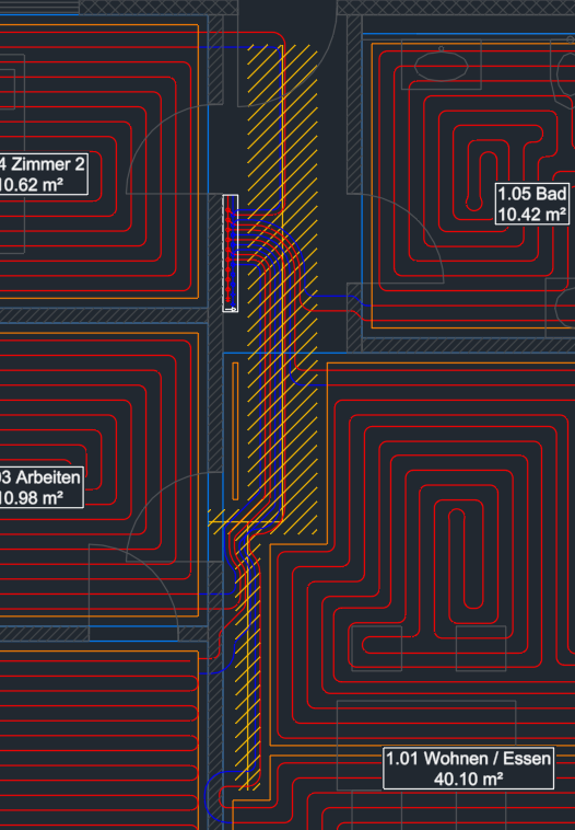
Goal: draw a corridor – for example in the hallway – through which the automatic leaders run to the manifold.
Steps
- In the section Leader corridor (for automatic connecting) enter the width (default 1000 mm, allowed 100 to 5000 mm) – or pick it with the pick button next to it: two points, their distance in plan becomes the width.
- Choose the edge: whether the clicked line is the center, the left or the right edge of the corridor (flush left/right). Optionally Spread across the width: the pipes then lie spread over the whole width instead of close to the edge.
- Click Insert leader corridor. Before the first click the insertion help shows the procedure.
- Click the corridor point by point – roughly is fine, it is a sketch.
- Enter = finish, the corridor is created. Esc discards only the segment at the cursor; the placed segments stay as the corridor.
Keys at the cursor
| Key | Effect |
|---|---|
| ← / → / ↓ | the clicked line is the left edge, the right edge or the center |
| A | "Width / wall offset": width from here and a wall offset |
| V | spacing increment on/off |
| Space | angle increment (45°) on/off |
| W, D | pick or type the base direction |
| Backspace | last point back |
Options
- If the run starts or ends on an existing corridor, it becomes a branch of that corridor; at the end of a corridor it extends it.
- A width typed in the palette applies to the running run only after Enter or the check mark next to the field – until then the field is highlighted.
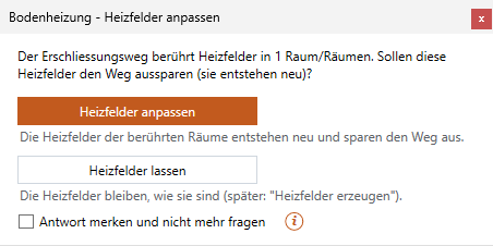
- If the corridor touches heated areas, the plug-in asks: Adapt heated areas (they are rebuilt and leave the corridor out with the edge distance) or Keep heated areas. With "Remember answer" it no longer asks; reset under gear menu › Heated areas at leader corridors.
Edit leader corridor
Goal: change a drawn corridor – surface, heated areas and leaders follow.
Below Insert leader corridor are the corridor tools:
| Button | What happens |
|---|---|
| Extend | Click the corridor near one end – the run continues there as when inserting; Enter or Esc creates the extension. |
| Draw branch | Start at a corner or segment of the corridor and draw the branch – it belongs to this corridor. |
| Change width | Click the corridor at a segment – on the side of the edge that should move –, then drag the edge or press A = enter the width. G switches between "whole corridor" and "this segment only". The flush edge stays. |
| Add vertex | Click the corridor at a segment and drag the new corner there (Space = across only). |
| Remove vertex | Click the corridor at a corner – it is removed, the neighbors are joined directly. A point where a branch is attached stays. |
| Delete segment | Click a segment – at the end the corridor gets shorter, in the middle the separated part becomes a corridor of its own; a branch is removed on its own. At the trunk with branches the plug-in asks: Whole corridor or This segment only. |
| Join | Click two corridors whose ends meet (they become one segment) or that touch as a tee (the second becomes a branch of the first). The first keeps edge and ID. |
| Move | Click the corridor, then base point and destination as with MOVE. Surface, heated areas and leaders follow. |
| Delete | Click the corridor – it is removed, the heated areas are rebuilt. Leaders through it stay and count as by hand. |
If loops are connected automatically through a changed corridor, the plug-in asks: Re-route (the leaders follow the corridor) or Keep (by hand). GstarCAD grips on the centerline of the corridor work the same way. Change the surface through the centerline – a deformed surface snaps back ("The surface of a leader corridor follows its centerline …").
All loops of a manifold
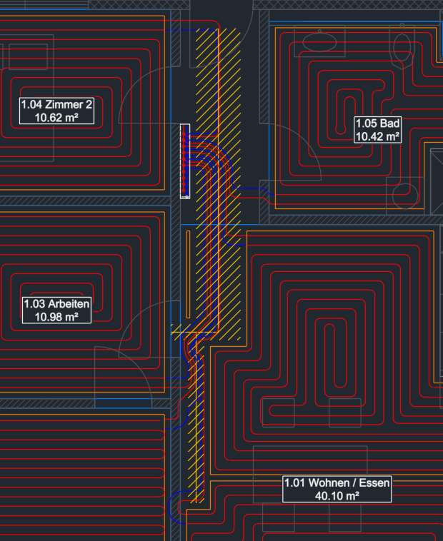
Goal: create the leaders of all (or selected) loops of a manifold at once – as an orderly bundle without crossings.
Steps
- Click All loops of a manifold. Before the first click the insertion help shows the procedure.
- 1 of 3: click loops (again = deselect) – or press Enter right away = all loops of the manifold. A click on a manifold takes all its loops.
- 2 of 3: click the manifold – skipped if it is unambiguous.
- 3 of 3 (only if there are leader corridors): the matching corridor is preselected. A click on another corridor switches (only one at a time), Enter accepts, the option NoCorridor connects without a corridor.
- If there are several sensible solutions, the cursor shows one in color: Tab or a digit switches, Enter accepts, Esc discards.
- The command line shows the result ("V1: 6 loop(s) connected, leaders 48.3 m, 0 crossing(s) among them.") and the length with leaders for every loop.
What happens: supply and return run together along the wall or in the leader corridor and branch off square to their loops. With all loops of a manifold the outlets are reordered so that nothing crosses ("3 loop(s) moved to other outlets …"). With selected loops only these are added; the others keep their outlet. Afterwards the pipes follow automatically when a loop is re-placed or the manifold is moved.
Options
If the manifold has too few outlets, the plug-in asks: Extend outlets to n (the manifold gets enough so all loops fit) or Without these loops (the command line names them). For large manifolds a progress window shows the status; Esc there cancels – nothing changes.
Individual loops
Goal: connect only the clicked loop – the leaders of the others stay as they are.
Steps
- Click Individual loops. Before the first click the insertion help shows the procedure.
- 1 of 2: click a loop.
- 2 of 2: manifold and leader corridor are preselected; the command line names both. Click another manifold, corridor or loop = switch. Enter = connect.
- Then the next loop right away; Enter = finish, Esc = cancel.
If the loop lacks an outlet, the manifold gets one more without asking ("Manifold V1 now has 7 outlets …"). The outlets of the other loops are never reordered; if the new loop crosses others, the command line says so – "All loops" reorders the outlets.
Leaders in the insulation layer
Goal: set whether leaders may run under a heated area.
| Check box | Effect |
|---|---|
| off (default) | The leaders run along the wall, around the heated areas; where that is not possible, they end before the first foreign heating pipe. |
| on | The leaders lie in the insulation layer below the screed and may cross heating pipes. "Check" reports the crossings as allowed. |
The setting applies to this drawing. When you change it, the leaders are recalculated (one undo step). The line below shows the status per manifold ("V1: 6 of 6 loop(s) connected, leaders 48.3 m.").