
Quick start: your first floor heating system
This page shows the shortest way from an empty floor plan to a connected loop, and the two most common changes afterwards. Every step has a picture; the details are in the linked tasks.
1. Open the palette and prepare the room
Ribbon › tab LuaCAD › Floor Heating. The palette opens at the edge of the drawing, the first time on the Rooms page.
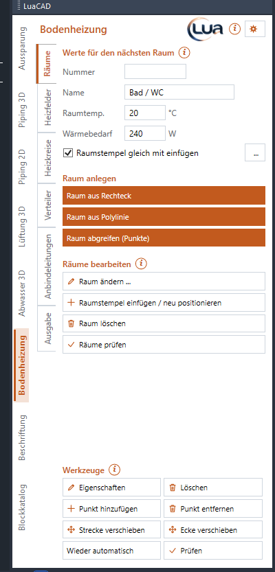
- Enter a number, for example 1.01 – it applies only to the next room and is empty again afterwards. Empty = the room has no number.
- Enter a name, for example Living (default "Room").
- Leave the room temp. at 20 °C – it is a value shown in the room tag and the list.
- The check box Insert room tag right away is on by default: the room gets its annotation right away.
2. Insert a room
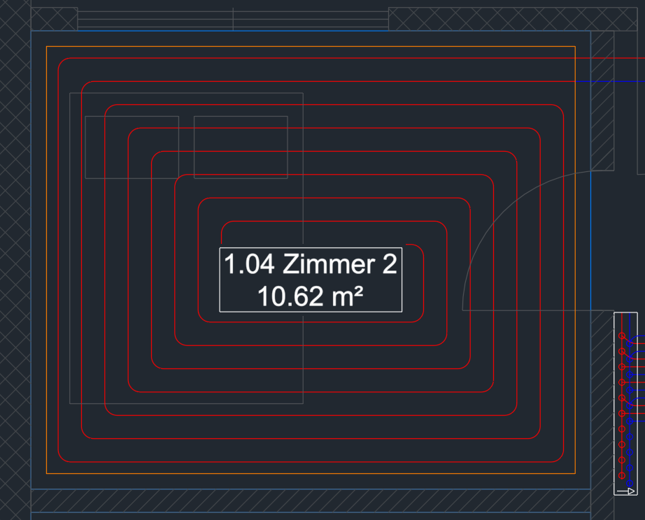
- Click Rectangular room.
- Click the first corner (1), then the opposite corner (2) – best with object snap on the inside corners of the walls.
- The room appears with its room tag (3); the command line shows area and perimeter. The next room follows right away; Enter finishes.
Rooms with angled walls are inserted from a polyline or corner by corner – see Room from polyline and Pick room.
3. Generate the heated area
Picture coming soonPlan view: the room with its heated area (1), the edge distance of 100 mm between wall and area (2)
- Open the Heated areas page. The edge distance is 100 mm by default.
- Click Generate heated areas and click into the room.
- The heated area (1) appears: the room, offset inward by the edge distance (2). The command line shows its area.
4. Place a loop
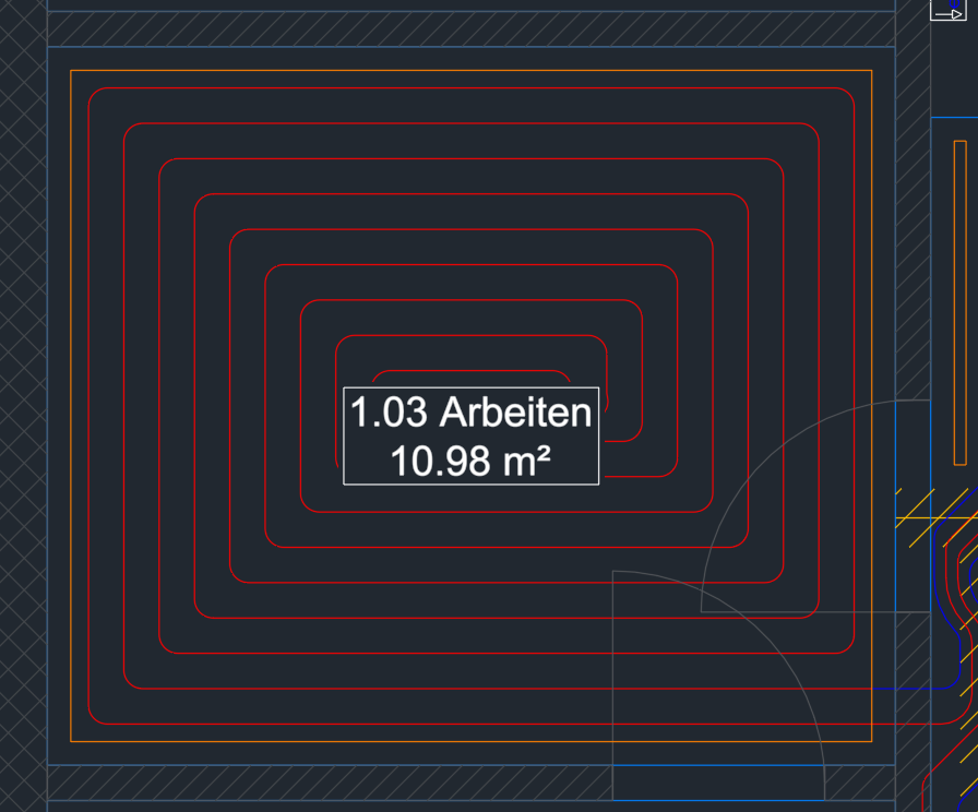
- Open the Loops page. Defaults: counterflow pattern, spacing 150 mm, pipe 16 x 2, maximum loop length 100 m.
- Click Place loop .... The dialog box with these values comes first – click OK.
- Move the cursor over the heated area: the loop is already visible. Click into the area.
- Click the connector point at the edge of the area (2) – supply and return leave there – or press Enter for automatic (on the side toward the manifold, without a manifold toward the center of the building).
- The loop is created (1); the next area follows right away, Enter finishes.
5. Insert a manifold
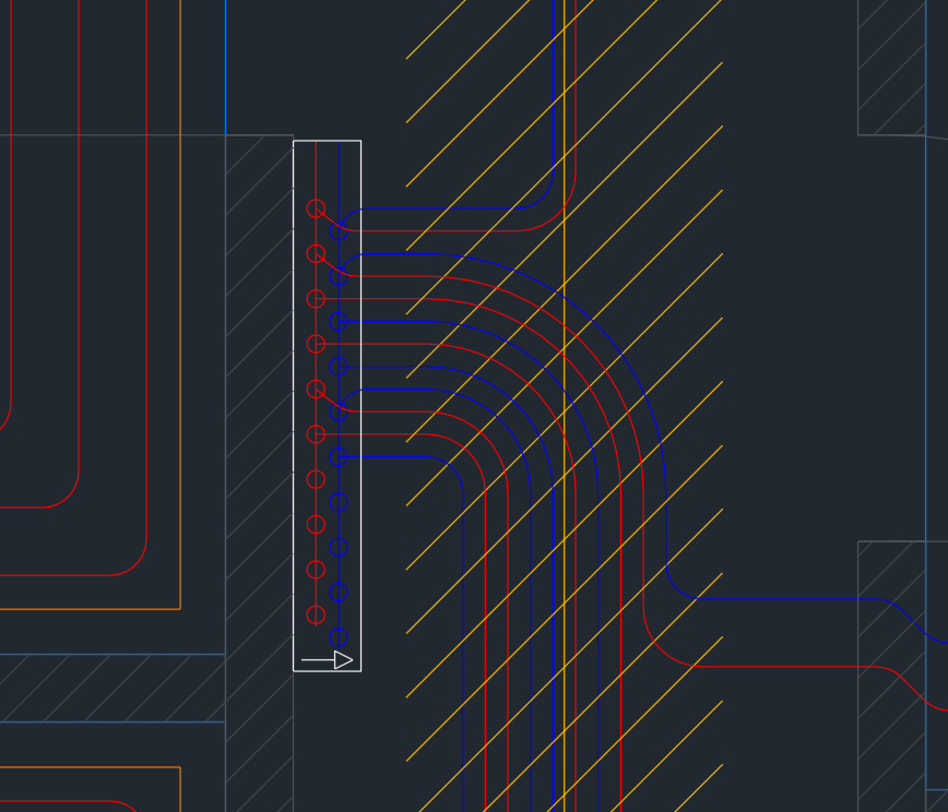
- Open the Manifold page. By default the number of outlets matches the loops ("to match the loops").
- Click Insert manifold …, then OK in the manifold dialog box.
- The manifold hangs at the cursor. R rotates it, W aligns it with a wall (two clicks). Click at the wall (1).
- The loops without a manifold get their outlet right away; their number now reads 1.01, for example. Enter finishes.
6. Connect the loops
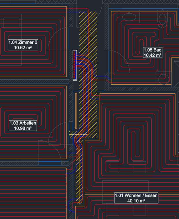
- Open the Leaders page and click All loops of a manifold at the bottom.
- Enter = all loops of the manifold. If there are several manifolds, click the manifold.
- If there are several sensible routes, the cursor shows one solution in color – Tab switches, Enter accepts.
- Supply and return run as a pair along the wall to every loop (2, 3). The command line shows the lengths.
7. Change a room with a grip
Picture coming soonPlan view: a room selected – a corner grip (1) dragged to the side; heated area and loop inside are rebuilt (2), the leaders follow (3)
- Click the outline of the room – the GstarCAD grips appear.
- Click a corner grip (1), drag it and click at the new position.
- At the end of the command the heated area and the loop are rebuilt (2), the leaders and the room tag follow (3). One U undoes everything in one step.
More in Editing rooms with GstarCAD.
8. Change a loop
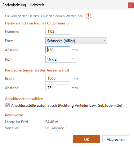
- Click Properties in the tools at the bottom (or Change loop ... on the Loops page) and click the loop.
- In the dialog box set, for example, Spacing to 100 mm or Pattern to serpentine – OK.
- The loop is re-placed with the new values; the leaders follow.
More in Changing a loop.
What next?
Video coming soon: The first floor heating
- Spots without heating (shaft, kitchen counter): Exclusion areas.
- Divide a large room into several areas: Divide area.
- Tighter spacing at the exterior wall: Choose perimeter zone.
- Leaders through a hallway: Insert leader corridor.
- Annotation and lists: Output.
- Esc cancels any function; another button in the palette cancels the running command and starts the new one. One U undoes the last step.