
Output
Item numbers
Goal: number the parts of a network and show the numbers in the plan – for parts list, shop and installation.
Every part of a network has a number; new parts get it by themselves at the end of every command. The item number is the balloon in the plan that shows this number. The buttons under Item numbers:
| Button | Effect |
|---|---|
| Create | Click a part – the whole network is renumbered from there. In the dialog box you choose the counting method, prefix and start number; the balloons are inserted. |
| Move | Click a balloon and drag it to a new place – the leader stays attached to the part. |
| Delete single | Click balloons – each one goes right away; Enter finishes. |
| Delete per network | Click a part – all balloons of its network go. |
| Delete all | All balloons of the drawing go (undo takes it back). |
| Show all | Every network that shows no balloons yet gets them at each numbered part. |
| Show single | Click a part; its balloon hangs at the cursor – click at the desired spot. |
Parts list
Goal: every part on its own row – for the shop: item, type, size, length, material, insulation, area and weight.
- Parts list (all parts of the drawing) or Per network and click a network (only that one; the next network, Enter finishes).
- Depending on the setting the list goes into the drawing as a table – the table hangs at the cursor, a click places it – or into a file (CSV or Excel).
- "…" next to it sets up the output: drawing or file, file name, separator, text height, template.
The check box Evaluate visible objects only leaves out parts on layers that are off or frozen – in all lists.
Bill of materials
Goal: the order list – identical parts on one row with quantity, plus the couplings between round ducts.
- Bill of materials or Per network and click a network.
- Place the table or save the file as with the parts list; "…" sets up the output.
By default the bill of materials combines identical parts across all systems; with the check box "per system" in the list options ("…") each system gets its own rows. Duct pieces are counted – they are prefabricated parts.
Across several plans
Goal: a bill of materials across several drawings – the whole project or the xrefs of the drawing.
- Bill of materials across the project … – check the plans in the dialog box (by default those of your own discipline) – or Bill of materials across xrefs … – the drawing and its external references, also nested, counted per insertion.
- Output as usual: as a table or a file.
The plans are only read, never opened. If a linked list is no longer current (a plan was saved afterwards), LuaCAD says so when the drawing is opened. The workflow is the same in all plug-ins – see Piping 3D › Lists across several plans.
Fitting symbols
Goal: show in plan view where a rectangular fitting sits – with the fitting symbol (Z line, with a frame at branches).
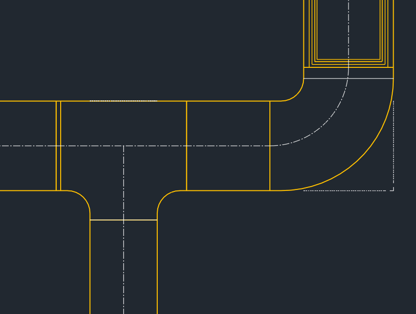
The switch Visible | Invisible under Symbols applies at once to all rectangular fittings of the drawing and to every new one. By default it is set to Invisible. The switch belongs to the drawing: undo takes it back, another drawing shows its own state.
Annotating
Goal: label parts with text from a template – for example system and size ("SUP 400 x 200"). The annotation follows the part when it is moved or changed.
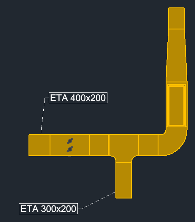
- Annotate and click a part (also another object).
- The annotation hangs at the cursor; place the text. "Template" in the action bar switches the template; Automatic takes the template of the part type (duct → duct size, round duct and flexible duct → round duct size).
- Done – or click the next part.
| Button | Effect |
|---|---|
| Templates … | Design content, form, height and layer of the annotation – with a preview on a part of the drawing. |
| Several … | One template on many parts: a network, a selection or the whole drawing – with a filter (part type, system, size, length) and position. |
| Edit | Click an annotation (or select it beforehand, also several): template, elevation reference, additional text, form, layer – also by double-click. |
| Check | Update all annotations and show those without a part. |
| Reassign | Click an annotation, then the part it belongs to. |
| Insulation, Elevation | Still grayed out – coming later. |
The default templates of ventilation are in the Ventilation folder: ducts (also with insulation), round ducts (also flexible ducts, "SUP Ø 200" or "DN 200"), fittings, duct accessories, networks, item numbers and elevations at bottom, centerline and top. Structure, look and elevation references of the templates are explained in Piping 3D › Default templates.
Dimensions
Goal: write the cross-section size of a duct or round duct into the plan – A over B or Ø.
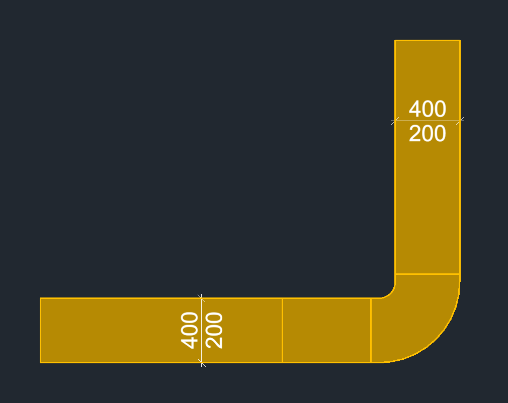
- Dimension and click a duct, a round duct or a fitting.
- The dimension hangs across the part at the cursor and slides along the axis; the Space changes the position of the value.
- A click places it. The dimension stays linked to the part – it moves with it, changes with it and is deleted with it.
The switch Visible | Invisible under Dimension shows or hides all dimensions of Ventilation 3D (visible by default); new ones follow. It belongs to the drawing – undo takes it back along. Symbol, size and unit of the value: gear menu › Attributes.
IFC export
The IFC export is on the ribbon › LuaCAD tab › Exchange ribbon panel. It writes all plug-ins into one IFC file (IFC4 or IFC2x3) – with classes, properties, IFC systems for each system and network, levels and connectors. Objects selected beforehand: only those.