
Concepts
Anyone who knows these terms understands every function of Ventilation 3D. The tasks refer back here when a term matters. General terms of all plug-ins (palette, system, layer, level, drawing units) are explained in Getting started › Concepts.
Duct run and fitting
At the top of the Ducts and Round ducts pages you choose what the next Insert creates:
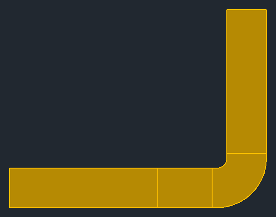
| Duct run / round duct run | Fitting | |
|---|---|---|
| What is created | A whole run: straight pieces up to the maximum length, an elbow at every corner, a reducer or transition where the size changes, an offset or offset elbows at an elevation change. | A single part: elbow, tee, offset, reducer, transition, wye, takeoff, end cap … – as the catalog provides it. |
| When to choose | For the normal routing of a duct. | For a special spot the run does not build by itself – for example a wye or a takeoff. |
| Dimensions | A × B (or D), elbow radius R and legs E/F. | Only the dimensions the part needs; the picture on the palette shows them. |
| At the cursor | Rubber band from the last point; Enter finishes. | The part itself; it connects, is inserted in-line in a duct or is placed freely. |
Both are 3D solids right away – unlike Piping 3D there is no line underneath. You edit the parts directly: with grips, Move, Move elevation and properties.
Duct, round duct and flexible duct
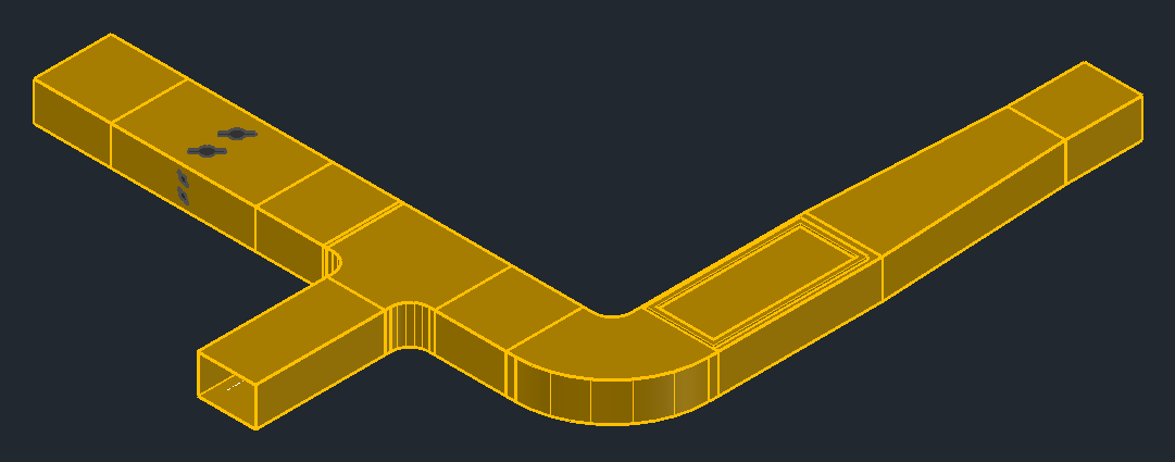
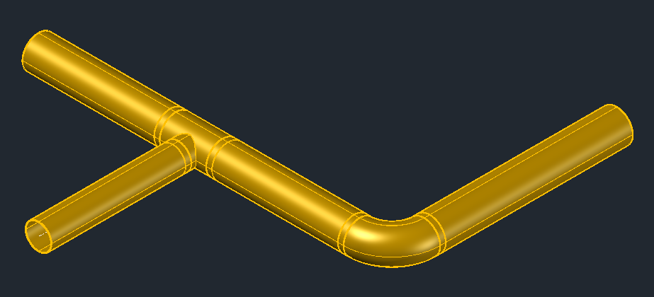
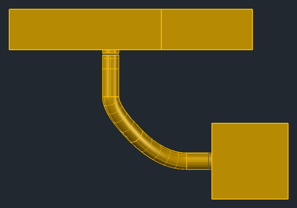
| Duct | Round duct | Flexible duct | |
|---|---|---|---|
| Cross section | rectangular, A × B (width × height) | round, diameter D | round, diameter D |
| Palette page | Ducts | Round ducts | Flexible ducts |
| Routing | straight pieces with elbows | straight pieces with elbows | smooth curve through vertices |
| Joining a duct | – | tee with transition or takeoff (Round ducts page › Branch to duct) | at an open round connector, for example a takeoff |
System
The system says which air flows in the duct – for example supply air or exhaust air. It sets color and layer of new parts (for example LuaCAD_LUE_SUP-Zuluft). The list shows only the ventilation systems; you create and edit them in the gear menu › Systems (see System).
- A part connects only to a connector of the same system; the connection marker names a different one.
- The crosshair button next to "System" picks system, catalog, material, insulation and size of a clicked part – so the next part matches the existing network. At the cursor, N matches only the system.
Catalog, material and classes
The catalog (Parameters page) decides which fittings and sizes exist and how long ducts and reducers become at most:
| Catalog | Meaning |
|---|---|
| EN 1505 / EN 1506 (made to measure) | The default: ducts and fittings as the sheet metal contractor fabricates them by material and size. Any size is possible; if A × B is not a preferred size per EN 1505, a note appears at the bottom of the palette. Pressure class and sheet thickness exist only here. |
| Manufacturer catalog | Only the sizes and fittings of this manufacturer. |
With it come the material, the air leakage class (per EN 1507 / EN 12237, the class per EN 16798-3 in brackets; B is the minimum, C the recommendation) and the hygiene class. A grayed-out list means the catalog does not know this class. In the made-to-measure catalog, material, pressure class and the largest edge determine the sheet thickness – or you set a fixed value. All of this goes to every new part and appears in lists and orders.
Justification and elevation
The elevation sets at which height a duct is created: as an absolute elevation, from level (level, reference level TOS, BOS, FF or FC and a value) or free (the elevation comes from the clicked point). The reference levels are explained in Elevations and references.
The justification says what this elevation refers to:
| Justification | The elevation means |
|---|---|
| top | the top of the duct – typical for a duct hanging below the slab |
| center | the centerline |
| bottom | the bottom of the duct – typical for a duct on the floor or on a bracket |
If the size changes along the run, this edge stays at the same height. Each page remembers its own justification (the Round ducts page has none – round ducts refer to the centerline).
Duct network, duct section and piece
- A duct network is all parts connected with each other – from the air handling unit to the last outlet. Item numbers, "Per network" for the lists, "Whole network" when deleting, and the diagnostics work on the network.
- A duct section is a straight run between two fittings (or a fitting and an open end). It can consist of several duct pieces. Grips, inserting in-line and Move work with the whole section.
- A piece is one straight duct piece, at most as long as the maximum length of the Parameters page (from the catalog or a fixed value). If a remainder shorter than the Min. length would be left at the end, it is divided evenly together with the previous piece – so no tiny parts are created.
Connector and connecting
Every part has connectors (V1, V2 …) with size and joint type. If nothing is attached, the connector is open – the network can continue there. A part at the cursor connects when you bring it close to an open connector with a matching system: it aligns with it, and the connection marker shows the lock and pull-away buttons.
- F (or the lock) holds the part there; after that the cursor only chooses the position.
- Z pulls it away along the axis – a straight piece is created in between.
- How close the cursor has to come and whether a part holds by itself after a while is set in the gear menu › Options › Snap.
The joint type per connector (rectangular: profile frame, M20, M30, M40, neutral; round: coupling, nipple, neutral) is in the Properties dialog box; its color is the same as that of the connector markers of custom parts.
Inserting in-line and surface-mounted parts
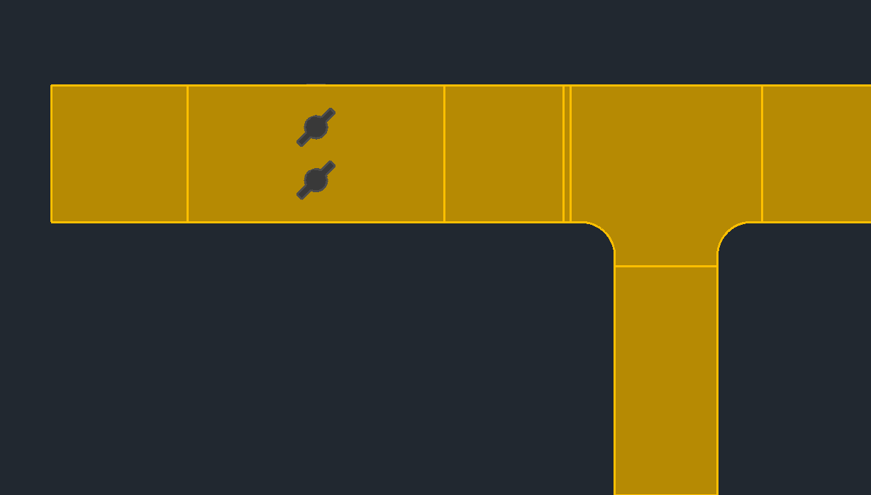
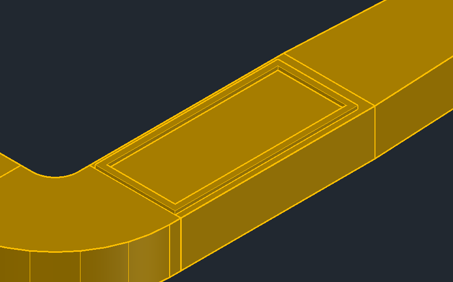
- A part the air flows through (damper, sound attenuator, fan, filter, reducer, tee, product, custom part) is inserted in-line: it divides the whole straight duct section, sits in between, and the ducts before and after it adapt. If it has a different connector size, a transition is added (at most as long as L1 or L2 of the connector transitions). A part inserted in-line is an in-line part; its grip in the middle slides it along the duct.
- A surface-mounted part (grille, air valve, takeoff, saddle) sits on one side of the duct; the duct gets an opening there and continues underneath. Beyond an open end it goes to the end face – the end gets an end cap for it.
Elevation change: offset and offset elbows
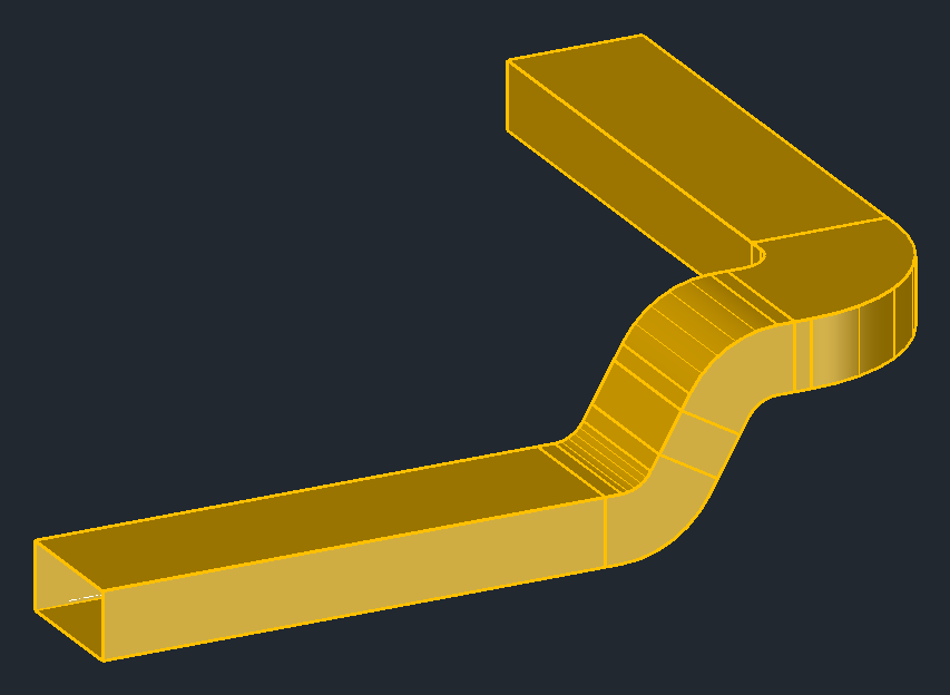
When a duct changes elevation – during the run with A, with Move elevation or Change properties – LuaCAD builds the change by itself:
| Elevation difference | What is created |
|---|---|
| up to the duct height (the side in the direction of the offset, the diameter for round ducts) | an offset fitting: two slopes, the cross section stays the same |
| larger | two offset elbows with the steepest standard angle (90°, 60°, 45°, 30°, 15°) that fits |
During a run this applies with "Elevation change angle" = Auto (the default); with a fixed angle the run always rises through two elbows at that angle. At a corner the corner stays at the placed point; the elevation change sits right behind the elbow or – at a right-angled corner with enough height – vertically in the corner. By default LuaCAD joins two parallel offset ducts of the same size with an offset fitting; in the gear menu › Options › Run you can choose the offset reducer instead.
Insulation
The insulation is a separate, semi-transparent solid around the duct or round duct. You choose the insulation material from the insulation table (gear menu); the thickness is proposed for ducts or round ducts and can be changed. "No insulation" has thickness 0. The list shows each material with its short name in parentheses, for example "mineral wool 50 mm (MW50)" or "thermal insulation 30 mm (WD30)". Flexible ducts are insulated only in the aluminum type. You show and hide all insulation solids of the drawing under Tools › Insulation; you change parts already inserted with Adjust insulation.
Ventilation parts and CAD commands
Ventilation parts behave like CAD objects: grips, MOVE, ROTATE, MIRROR, COPY and the Properties palette work. At the end of the command LuaCAD updates the adjacent parts – in the same undo step.
- A 3D solid is never stretched: a stretched part jumps back. You change the length with the grip at the open end or in the properties.
- MOVE of an in-line part alone works like its grip: along the duct, and across it the whole line moves.
- What happens to the rest of the network when you select with CAD commands (ask, only the part, whole network) is set in the gear menu › Options › Edit.
- If a part lies on a locked layer, LuaCAD does not change it and says so.
The preview window
The preview window "Ventilation 3D - Preview" floats next to the palette and shows the part you are choosing in 3D – the way it will be inserted: in its profile and the color of its system, the insulation see-through, plus the dimensions with the same letters as the fields in the palette (A, B, L, R …).
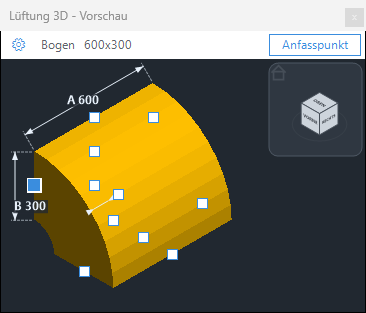
- When it appears: on the pages Ducts and Round ducts as soon as the switch is set to Fitting and a fitting is chosen, and on the page Duct accessories for every chosen part. When you change a value in the palette (profile, angle, length …), the window shows the part again a moment later.
- Header: the gear on the left, the name of the part in the middle, Base point on the right (only when the part has base points).
- Cube at the top right of the picture: click a face, edge or corner = view from there; the house above it = southwest isometric view, zoomed to fit.
- Mouse in the picture: dragging with the left button rotates (so does Shift + middle button), the middle button pans, the wheel zooms toward the pointer, a double-click with the middle button zooms to fit. Keys keep going to the drawing – the window never takes the focus.
- Gear menu (also right-click into the picture): Visual style (2D wireframe to X-ray), View parallel or perspective, Rotate (the part follows the mouse or the other way round), View direction, Show dimensions, Choose base point (top view), Zoom to fit and Place next to the palette (after you have moved the window).
- Grips: the white squares on the part are its base points, connectors have their own color. A click on a grip sets the point by which the part hangs at the cursor the next time you insert it; at the cursor Space keeps cycling.
- Show and hide: gear menu of the palette › Preview window › Show or Hide. Closed with the cross, it stays closed until you choose Show – that brings it back with the chosen part. LuaCAD remembers position, size, visual style and dimensions.