
Duct accessories, products and custom parts
Inserting a part in-line
Goal: place a damper, a sound attenuator, a fan, a manufacturer product or a custom part in an existing duct. The part is inserted in-line: it divides the whole straight duct section and sits in between – the ducts before and after it adapt.
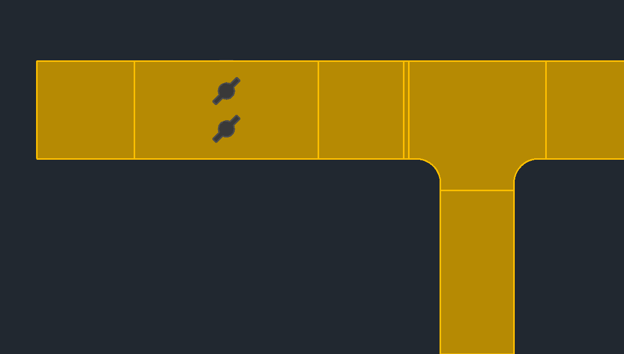
- Choose the part on the palette – Duct accessories, Products or Custom parts page – and click Insert. The first time, the insertion help appears with a picture.
- Point at a duct until the part aligns with it, and click – step 1 of 2.
- Slide the part along the duct to the right spot and click (1) – step 2 of 2. The left/right arrow turns it around, Esc goes back to step 1.
- At an open connector of the same system it connects instead: F holds, Z pulls it away – a straight piece is created in between.
- Away from a duct it is placed freely: R rotates with the mouse, D takes an angle, A sets a distance to a point.
- The Space shows the base points to click. Enter = finish, Esc = cancel.
Keys at the cursor
| Key | Effect |
|---|---|
| ← / → | turn around (free: rotate in quarters) |
| ↑ / ↓ or R | on the duct or connected: rotate about the axis; free: R rotates with the mouse |
| F / Z | hold at the connector / pull away; pulled away, A asks for the length |
| D / W | free: type an angle / pick it with two clicks |
| T | free: tilt in 45° steps |
| Space | show the base points – the next one yellow, a click takes it |
| N | match the system of a clicked part |
Placing a grille, air valve or takeoff
Goal: place a grille, an air valve, a takeoff or a saddle on one side of a duct or round duct – the duct gets an opening there and continues underneath.
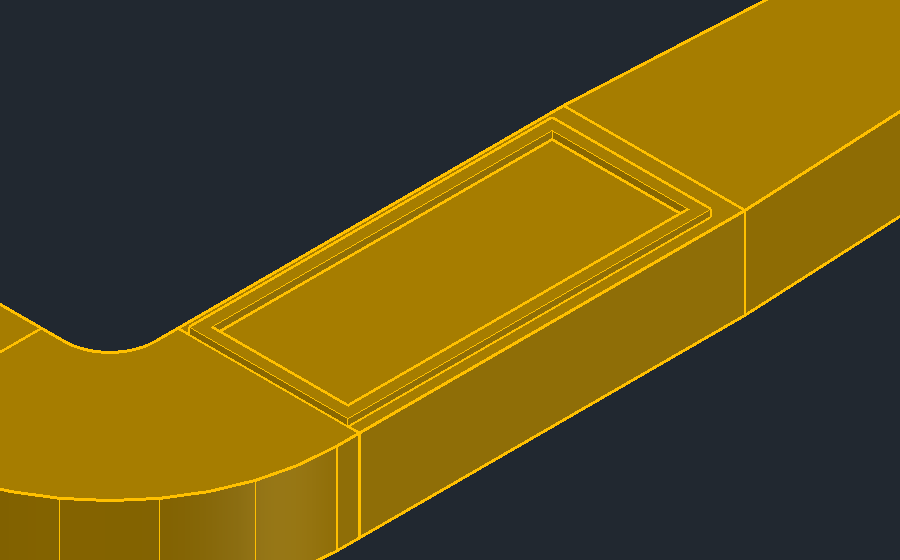
- Choose the part: on the Duct accessories page grille or air valve, on the Ducts/Round ducts page a takeoff or saddle as a fitting. Insert.
- Click the duct (1 of 2) – the part then sits on the whole straight run.
- Slide the part along. R or the up/down arrow switches the side (top, left, bottom, right), the left/right arrow rotates it on the surface.
- Beyond an open end it goes to the end face: the end gets an end cap for it (or it sits on the existing end cap).
- A click inserts (2 of 2). Esc goes back to step 1, Enter = finish.
On a vertical duct (riser duct) the cursor chooses the elevation in a 3D view; in plan view the elevation of the palette applies ("free": the middle) and the cursor chooses the side.
Several identical parts in a row: Multiple placement.
Setting up a duct accessory
Goal: define a duct accessory made to measure – damper, sound attenuator, grille, box, fan …
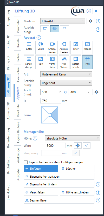
- Click the symbol of the accessory at the top.
- Choose the type – for a duct (rectangular) or a round duct (round) – and the designation (subtype, for example rain cap, louvered cap or column cap for the roof cap).
- Enter the dimensions; only the rows this accessory needs are shown.
- For accessories the air flows through, check the insulation and the connector transitions.
- Insert – see Inserting in-line or Surface-mounted.
| Accessory | Dimensions on the palette | At the duct |
|---|---|---|
| Grille | L, B, quantity, spacing method, spacing | surface-mounted |
| Air valve | A × B or D, quantity, spacing method, spacing | surface-mounted |
| Plenum box | A × B or D, the box dimensions (L, H) | connected |
| Discharge plenum | A × B or D, B × H × T, number and spacing of the connectors, edge distance, position of the connectors and of the outlet | connected |
| Filter, damper, airflow regulator, fan, flexible duct connector | A × B or D, L, connector transitions, insulation | in-line |
| Sound attenuator | as above; round also the box insulation and the stub length a | in-line |
| Weather louver | A × B or D | at an open end or on the side |
| Roof cap | A × B or D, L; rectangular rain cap: shape; louvered and column cap: louvers and cover type | at an open end |
Multiple placement
Goal: place several identical parts (grilles, air valves, takeoffs) in a row on a duct in one go.
| Setting | Effect |
|---|---|
| Quantity | How many identical parts are created in a row along the axis, starting with the first. |
| Spacing method | What the spacing below means: With spacing = center to center; With gap = the free space between two parts; Spread over (asymmetric) = the length the parts divide into equal sections (step = length ÷ quantity); Spread over (symmetric) = the whole length of the row from the first to the last part, outer edge to outer edge. |
| Spacing | The value for the spacing method, in drawing units; the crosshair button picks it with two points. |
For the discharge plenum these are the connectors on the box, spaced center to center (only "With spacing" there). If the length of the row is not enough for all parts, only the first is inserted and the command line says so.
Connector transitions
Goal: set the maximum length of a transition when a duct accessory, a product or a custom part has a different connector size than the duct.
Under Max. lengths of connector transitions (Duct accessories, Products, Custom parts pages): L1 at the first, L2 at the second connector, 300 mm each by default; the arrow swaps both. If there is no straight duct piece next to it that can take the transition, the part is inserted without a transition and the command line names the spot – then adjust by hand.
Inserting a manufacturer product
Goal: insert an article from a manufacturer catalog – with order number and exact geometry.
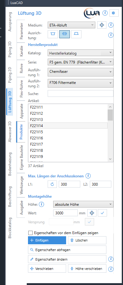
- Products page: choose the catalog (for example fire dampers, dampers and airflow regulators, sound attenuators, filters, air terminals) and within it the series (product group in brackets).
- Narrow down with the variants: each list shows only values for which articles exist; "(all)" shows every one.
- Use the search to find a size quickly, for example "400x200" – the list filters as you type.
- Choose an article; the order number is in the tooltip and later in the list (where the manufacturer supplies none, it stays empty).
- Insert (or double-click): the product hangs at the cursor, connects to an open connector or is inserted in-line in a duct or round duct.
Inserting a custom part
Goal: connect your own DWG or DXF – for example an air handling unit – to ducts with its connectors.
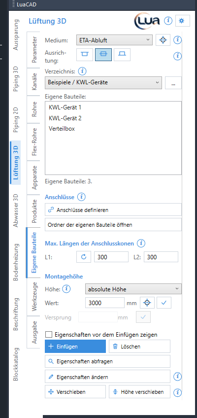
- Custom parts page: choose the folder. By default "Examples / Air handling units" and "Examples / Residential ventilation units" are in it (supplied, read-only). "…" adds your own folders (also network drives), names them or removes them.
- Choose the part in the list – below it you see its picture and how many parts the folder contains.
- Insert (or double-click): the part connects to an open connector or is inserted in-line in a duct. The Space switches the connector at the cursor.
Open the custom parts folder shows the folder in Windows Explorer with the chosen part selected. The folder list is the same in all plug-ins – see The custom part folders.
Defining the connectors of a custom part
Goal: tell a custom part where its duct and round duct connectors are – without connectors it cannot be inserted.
- Open the DWG of the part.
- Custom parts page › Define connectors – the custom part wizard starts in this drawing.
- Mark each connector: round with a circle, rectangular with a line cross. The color sets the joint type – rectangular: M20 turquoise, M30 brown, M40 violet, profile frame light green, neutral gray; round: coupling light blue, nipple dark blue, neutral gray.
- Save. After that the part connects to ducts.
The steps of the wizard in detail: Piping 3D › Defining connectors.
Properties before inserting
Goal: give every new part property fields right away (plant, construction phase, tag …).
- Duct accessories, Products, Custom parts pages: the check box Show properties before inserting (off by default) opens a dialog box with the fields before the cursor; the values go to the part, LuaCAD counts the tag up. Esc at the cursor leads back to this dialog box.
- Ducts, Round ducts, Flexible ducts pages: the area Property fields of the next pipe (the same wording in all plug-ins) – the values go to the network of the run where it does not carry them yet.
Which fields exist is set in the gear menu › Property fields; the fields of a whole network are set with gear menu › Property fields of a pipe … (click a part of the network).