
System elevations and crossings
Creating system elevations
Goal: set the system elevations of the drawing – for example "in the floor", "in the wall", "below the ceiling".
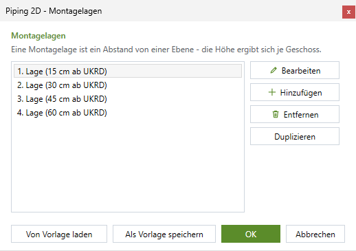
- Gear menu › System elevations. The System elevations dialog box opens – the same system elevations as in Piping 3D; they belong to the drawing.
- Add or Edit (or double-click): abbreviation (for example "D1"), name, under "Position in the level" the reference level (for example FF or BOS) and the distance from it.
- Remove, Duplicate; Save as template stores the list in your settings, Load from template replaces the list of this drawing with the stored one – so every drawing gets the same system elevations.
- OK. Pipes already drawn stay as they are – they keep their system elevation, linetype, elevation symbols and gaps. New system elevations apply to new pipes; a renamed system elevation is only taken over by the palette. An elevation table in the drawing then shows the current list.
Example: The drawing has two pipes in "1st elevation". You rename it to "below ceiling". The two pipes still carry "1st elevation" – the command line says "2 pipe(s) carry a system elevation that no longer exists", Check lists them as a note, and Change system elevation shows "1st elevation (no longer exists)". To move them to the new system elevation, select them and assign "below ceiling" with Change system elevation.
The list is sorted by height: the higher system elevations first. This order decides at crossings and elevation changes which system elevation lies on top. Piping 2D still draws no elevation – it only takes effect when converting to 3D.
Crossings
Goal: understand and control where pipes are broken.
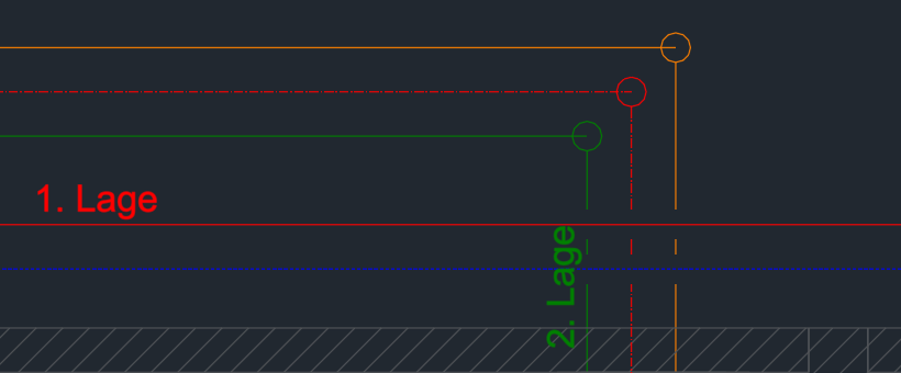
Where a pipe crosses a pipe on a higher system elevation, Piping 2D breaks the lower one there with a real gap (default 50 mm), the upper one runs through. On the same system elevation there is no gap. This happens by itself with every change: drawing, moving, copying, deleting, changing the system elevation. For lists, annotation and conversion the pipe stays one pipe; if you select one piece, the others come along.
| Where | What you do |
|---|---|
| System elevations page › Update crossings | Break all crossings of the drawing again – for example after a change in an xref. The command line names the number of crossings and of pipes written anew. |
| Gear menu › Elevation marking › Break crossings automatically | On and off; off = all gaps are closed ("Update crossings" then reports "crossings automatically off"). |
| Gear menu › Elevation marking › Gap length | The length in the drawing. For the plot to ISO 6412 at least 5 × the line width on paper – at 1:50 and a 0.5 mm line about 125 mm. |
Elevation change
Goal: take a pipe to another system elevation at a corner.
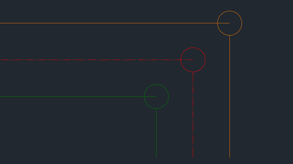
- While drawing press A and choose another system elevation – or change it in the palette. It applies from the next click.
- At the corner the elevation change circle is created (default 60 mm diameter): the upper pipe runs to the center of the circle, the lower one ends at its edge.
- The same happens when you connect to the end or the middle of a pipe on another system elevation, join two system elevations with Connect, or change one half with Change system elevation. At a tee the pipe that runs through stays whole.
The circle follows the moved pipe (grip, MOVE, Move); the pipe not selected keeps its alignment, the corner moves to the intersection point. If both pipes have the same system elevation afterwards, the circle disappears. Set its size in the gear menu › Elevation marking › Circle at elevation change. The bill of materials counts an elevation change as two elbows (or a tee and an elbow).
Elevation marking
Goal: set how each system elevation looks in the plan – linetype, elevation symbol, circle, gap.
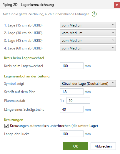
- Gear menu › Elevation marking.
- Per system elevation the linetype: by system, continuous, dashed, dash-dot, hidden (short dashes), center, dotted. Default: first system elevation by system, second dashed, third dash-dot, all others by system.
- Circle at elevation change: diameter in the drawing.
- Elevation symbol at the pipe: "Symbol shows" the abbreviation of the system elevation (German practice) or slashes (Swiss practice – as many as the position of the system elevation in the list); the text height on the plot (mm on paper) and the plot scale give the text height in the drawing (1.8 mm × 50 = 90 mm); the slash length.
- Crossings: break automatically on/off and the gap length.
- OK – everything applies right away to the existing pipes of this drawing too (linetype, elevation symbols, elevation table, crossings) in one undo step.
Every setting: Reference › Elevation marking.
Elevation symbols
Goal: show in the plan on which system elevation a pipe lies.
- System elevations page › Draw elevation symbols. Before the first click the insertion help shows the procedure.
- Click the start of a line next to the pipes – or click a single pipe directly.
- Click the end point of the line: every crossed pipe with a system elevation is selected.
- Drag the symbols along the pipe into place and click (1); the option Mirror in the command line puts them on the other side.
- Then the next line right away; Enter = finish, Esc = back.
By default the symbol shows the abbreviation of the system elevation, readable (never running to the left or downward); with "slashes" as many slashes as the position of the system elevation in the list. An elevation symbol follows its pipe; moved by itself it stays on it.
Delete elevation symbols: click the pipe or cross several with a line – their elevation symbols are removed.
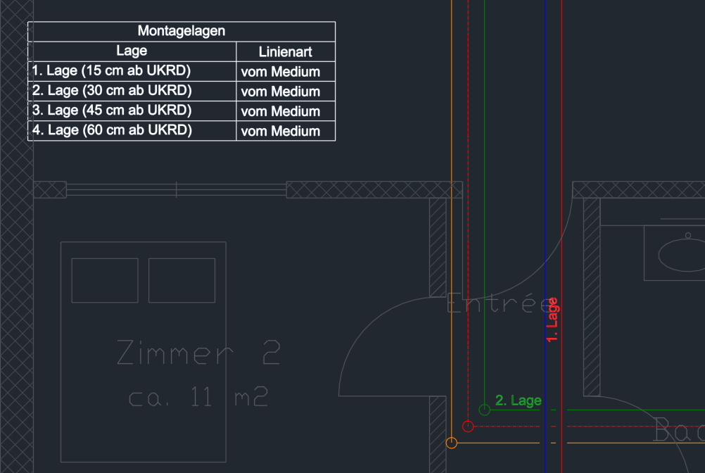
Elevation table
Goal: place a table in the plan that explains abbreviations and linetypes.
- Output page › Elevation table.
- Click the upper left corner of the table.
- The table shows "abbreviation – name" and the linetype per system elevation; with slashes an extra column with the symbol in front. It lies on the layer
LuaCAD_BES_Listen.
If there is already an elevation table, it is renewed in its place. Without system elevations the command line says that you have to create them first.
Applying elevation marking
Goal: bring another drawing up to date with the elevation marking.
The elevation marking is a setting for all drawings. In the active drawing a change takes effect after the dialog box by itself; a drawing that was not open then is brought up to date by the System elevations page › Apply elevation marking: linetype per system elevation, elevation symbols, elevation table and crossings for all pipes of this drawing. The command line names how many lines got a new linetype and how many elevation symbols, tables and crossings were renewed.