
Output
Item numbers
Goal: number the parts of a network – for parts list, isometric and installation.
When you generate 3D, the parts of a network get their numbers by themselves. The buttons under Item numbers:
| Button | Effect |
|---|---|
| Create | Click a part of the run – all parts are numbered again from there (type, start and prefix in the dialog box), the balloons are inserted. |
| Move | Click a balloon and drag it to a new place. |
| Delete single | Click a balloon – only this one is removed. |
| Delete whole network | Click a balloon – all balloons of its network are removed. |
| Delete all | All balloons of the drawing are removed. |
| Show all | Insert a balloon for every numbered part without one. |
| Show single | Click a part and drag its balloon to the place you want. |
Parts list
Goal: every placed part in one row, with its item number.
- Parts list (all parts of the drawing) or Per network and click a pipe (only its network).
- Depending on the setting the list comes as a table into the drawing – the table hangs at the cursor, a click places it – or as a file (CSV or Excel).
- "…" next to it sets the output: drawing or file, file name, separator, template.
The check box Evaluate visible objects only leaves out parts on layers that are off or frozen – in all lists.
Bill of materials
Goal: the order list: equal articles combined, pipes summed up by length.
- Bill of materials (whole drawing) or Per network and click a pipe.
- Output as for the parts list; "…" sets it up. By default without the system – with the check box "per system" in the list options it is grouped by system.
Lists across several plans
Goal: a bill of materials across several drawings of the project or across the xrefs of the drawing.
- Bill of materials across the project … or Bill of materials across xrefs ….
- Check the plans in the dialog box (by default your own discipline). For xrefs every insertion counts, also nested ones.
- Output as usual. The plans are only read, never opened; a linked list reports when a plan has changed since.
Cut list
Cut list optimizes how the pipes are cut from stock lengths: how many stock lengths, which pieces from which length, which offcuts remain – including the saw cut width.
Annotating
Goal: label parts with text from a template – nominal size, system, elevation, article … The annotation follows the part, even when it is moved or placed again.
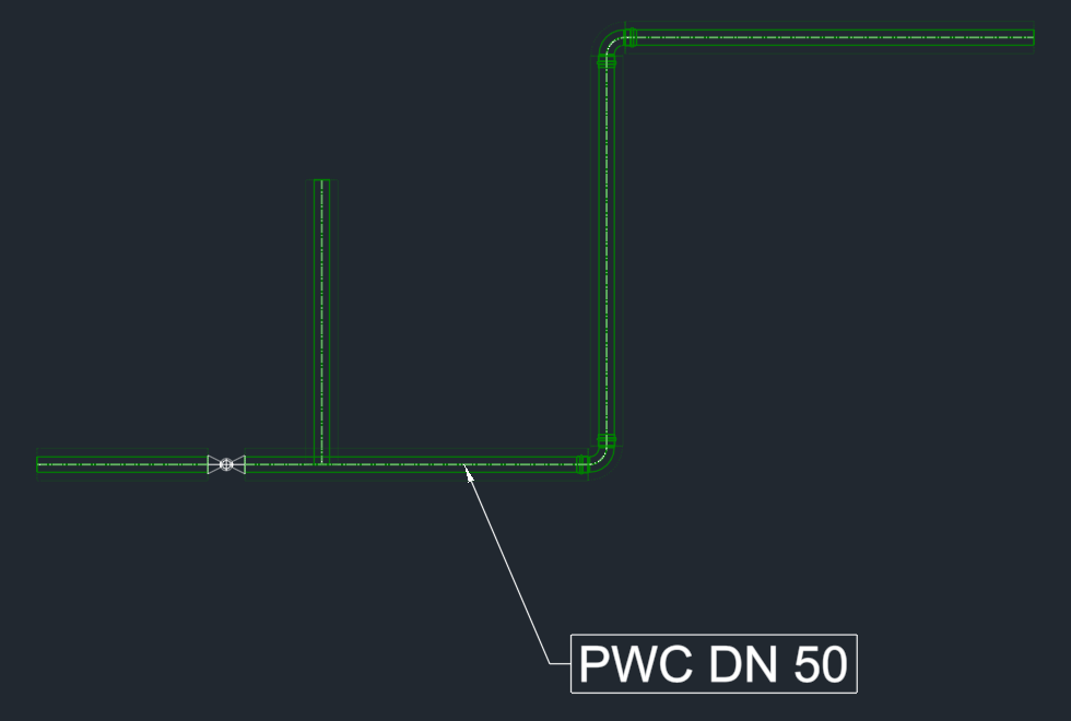
- Annotate and click a part (also an object from outside LuaCAD).
- The annotation hangs at the cursor; place the text. "Template" in the action bar switches the template.
- Done – or click the next part.
More buttons
| Button | Effect |
|---|---|
| Templates … | Design content, form, height and layer of the annotation – with a preview on a part of the drawing. |
| Several … | One template on many parts: a network, a selection or the whole drawing – with a filter (part type, system, DN, length) and position. |
| Edit | Click an annotation (or select several beforehand): template, elevation reference, additional text, form, layer – also by double-click. |
| Check | Update all annotations and show the ones without a part. |
| Reassign | Click an annotation, then the part it belongs to. |
| Elevation | Click a part – write its elevation (absolute or from the level edge, centerline, top or bottom). |
Default templates
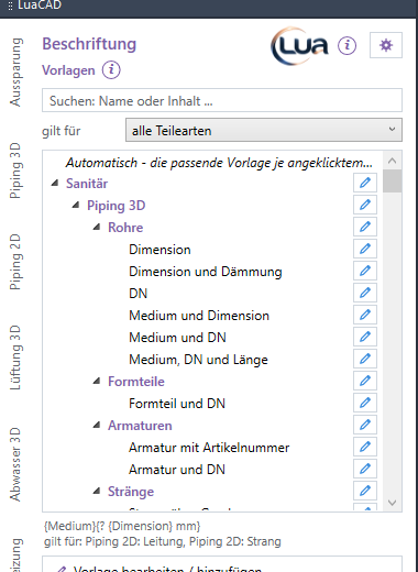
The supplied annotation templates are listed in the Annotation palette in folders: first the discipline (plumbing, heating, cooling, ventilation, process piping, openings, general), inside it the plug-in and inside that one folder per part type – a matching annotation for every part. The content follows the construction drawings of daily practice: short, one value per purpose.
| Folder | Templates (example) |
|---|---|
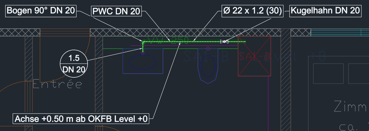
| Piping 3D › pipes | system and size ("CW Ø 28 x 1.2"), size, size with insulation ("Ø 28 x 1.2 (30)" – insulation thickness in mm in brackets), nominal size, system and nominal size, with length |
| Piping 3D › fittings | fitting and nominal size ("elbow 90° DN 25") |
| Piping 3D › valves | valve and nominal size, valve with article number |
| Piping 3D › risers | riser across levels (the level where the riser continues) |
| Piping 3D › item numbers | item number with nominal size (divided circle) |
| Piping 3D › elevations | centerline absolute, from the level, from the level of the spot, above sea level; bottom / centerline / top from BOS |
| Piping 2D | lines (system and size, system and layer, with length), risers, manifolds |
| Wastewater | lines (nominal size and slope, diameter and slope, type 1–3, flow …), stacks, fixtures, manholes, elevations – always as invert elevation |
| Ventilation | ducts ("SA 400 x 200", with insulation), round ducts (also flexible ducts, "SA Ø 200" or "DN 200"), duct fittings, equipment, risers, item numbers, elevations for bottom, center and top |
| Floor Heating | rooms (room tag), loops, manifolds |
| General | description, article number, item numbers, blocks and fixtures, other objects, elevations (arrowhead) |
The templates of Piping 3D and 2D are listed under plumbing, heating, cooling and general, each as its own copy – the annotation is placed on the layer of that discipline.
Elevations: "absolute" measures from the origin, "from the level" from the finished floor (FF) of the level of the drawing, "from the level of the spot" from the finished floor of the level the spot lies in, "above sea level" from the sea level of ±0 – enter it in the template (template editor, section elevation reference). The levels and their heights are set in the project (project palette › levels).
Default look: frame around the text, background mask, font Arial, text height 125 mm in model space (2.5 mm on a 1:50 sheet; LuaCAD converts in a drawing in cm or m), text and lines in color 7 (black on white, white on a dark background), layer of the discipline (LuaCAD_SAN_Beschriftung, LuaCAD_HZG_Beschriftung, LuaCAD_LUE_Beschriftung …).
| Setting | Where | Effect |
|---|---|---|
| Annotation style (font, height, colors, lines, layer, background mask) | Button at the right of each row of the template list | How the annotations of this template (or of all templates of a folder) look. |
| Form (frame, no frame, circle, divided circle) | Template editor ("Edit / add template") | Whether the text stands in a frame, without a frame or in a circle. |
| Content, folder, applies to | Template editor | What the annotation shows, where it is listed and on which parts it is offered. |
Automatic takes the template of the part type of the clicked part: pipe → system and size, elbow and tee → fitting and nominal size, valve → valve and nominal size, duct → duct size, round duct and flexible duct → round duct size.
Elevation symbols
Goal: show in the plan on which system elevation a pipe lies.
- Elevation symbols › Draw and click a pipe – or drag a line across several. The symbol of its system elevation is placed along the pipe.
- Delete: click a pipe or drag a line – its elevation symbols are removed.
- Elevation table inserts the table of system elevations (symbol, name, reference) into the drawing or updates it.
IFC export
The IFC export is on the ribbon › LuaCAD tab › Exchange ribbon panel. It writes all plug-ins into one IFC file – pipes parametric, with connectors, the property fields and the manufacturer data. If required fields are empty, LuaCAD tells you first.
Checking for clashes
Goal: find clashes between pipes, ducts, drainage and – if you want – the building elements of an IFC.
- Tools page › Clashes section: choose the check set and the scope (this drawing only, against xrefs, also xref against xref).
- Check.
- The list shows every clash; a click on a row shows the place.
- Accepted, resolved and comments are kept for the next check; what has disappeared is marked resolved.