
Generating 3D and display
Generate 3D
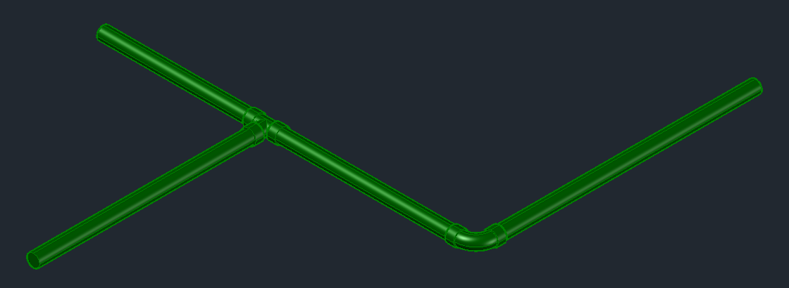
Goal: place pipes, elbows, tees and reducers from the catalog on selected routing lines. What happens exactly is explained in the Basic concepts.
- Click Generate 3D – the button is on the Pipe, Risers/connectors, Symbols, Custom parts, Products and Tools pages.
- Click pipes or drag a selection window; Enter. The whole run of the pipe gets its 3D – everything connected to it.
- If the catalog offers several suitable parts at a spot, the Fitting selection dialog box asks: double-click or OK takes the selected part, "reuse" takes it for every identical spot in this run, Cancel takes the first part of the list.
- At the end the parts are in the drawing, numbered. Whatever could not be built as it should appears in the issues list at the bottom right – with "Show" for each row.
Options
- Gear menu › Generate 3D: "Ask when several are selected" or "Do not ask" – whether LuaCAD asks separately for several selected networks.
- Gear menu › Pipe settings: stock length and coupling.
- Tools page › Insulation: visible or invisible.
Video coming soon: Generating 3D
Delete 3D
Goal: remove pipes and fittings and work with the routing lines again.
- Click Delete 3D.
- Click pipes or drag a selection window; Enter.
- The pipes and fittings of the selected networks are removed, the routing lines become visible again and can be changed further.
Video coming soon: Deleting 3D
Pipe lengths and couplings
Goal: set the lengths in which pipes are created when the 3D is generated.
- Gear menu › Pipe settings, page Pipe lengths.
- Per catalog and nominal size the pipe length – by default the manufacturer's supply length. If a pipe is longer, "Generate 3D" divides it into stock lengths of this length.
- With coupling: between two stock lengths sits a coupling from the catalog (same DN, same diameter as the pipe). Without the check mark – or if the catalog has no suitable coupling – the stock lengths butt together without a part.
Video coming soon: Pipe lengths and couplings
Switching the display
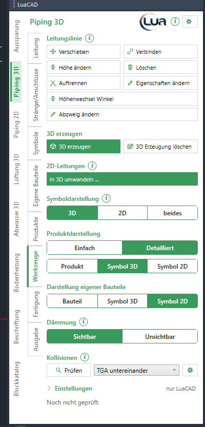
Goal: show what is needed right now – for example only 2D symbols for plotting, or symbols instead of real product bodies. The switches on the Tools page change all parts of the drawing at once, without a selection, and also apply to newly inserted parts. The highlighted part is the one currently in effect.
| Switch | Settings | Effect |
|---|---|---|
| Symbol display | 3D · 2D · both | Symbols as 3D bodies, as 2D line drawings (for plotting) or both together (default). |
| Product display | Simple · Detailed | The geometry of the catalog parts; pipes with 3D are rebuilt. |
| Product display | Product · Symbol 3D · Symbol 2D | Products and generic valves with their body or with the assigned symbol – never both. |
| Display of custom parts | Part · Symbol 3D · Symbol 2D | Custom parts with their DWG or with the assigned symbol. |
| Insulation | visible · invisible | Insulation as a body around the pipes or none; pipes with 3D are rebuilt. The insulation thickness stays at the pipe and in the lists. |
Video coming soon: Switching the display
Converting 2D to 3D
Goal: continue a plan from Piping 2D in 3D without drawing it again.
- Tools page › 2D pipes › Convert to 3D ….
- Select the 2D pipes (click or selection window); Enter.
- In the dialog box set the elevation per system elevation and catalog and pipe spec per system; on the Options tab choose whether the 2D objects are deleted or kept afterwards (by default with a prompt).
- OK: each 2D pipe becomes a routing line at the elevation of its system elevation; an elevation change becomes a vertical segment, a symbol the chosen generic valve, a riser a riser, a 2D fixture the same fixture in 3D.
Video coming soon: Converting 2D to 3D