
Output
Annotations are attached to their part and stay up to date when it changes – even after "Delete 3D" and generating again. The parts list lists every item separately, the bill of materials adds up identical parts.
Annotation
Goal: give a part a ready-made annotation – diameter, slope, spot elevation, stack, fixture …
- Output page: choose a tile under Annotation.
- Single: click a part and place the annotation. Or All: click a part – all matching parts of the drainage network are annotated.
- The annotation follows its part when it changes.
| Tile | What it shows |
|---|---|
| Type 1 | circle with item number and diameter |
| Type 2 | box with pipe length, item number and diameter |
| Type 3 | product line (short code) and diameter on a pin |
| Type 2 cut | like Type 2, for cut pipes |
| Qww | wastewater flow rate of the section |
| Spot elevation | elevation: top, centerline or invert (see Spot elevation and elevation) |
| Stack | short name of the stack with its fixtures |
| Fixture | short name of the fixture (WT, WC, DU …) |
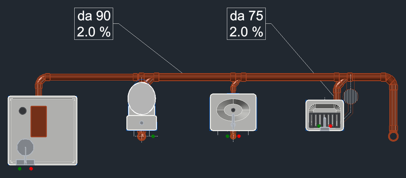
| Slope | slope and flow direction of the pipe |
| Manhole | data of a manhole or trench drain |
| Center to center | dimension from pipe center to pipe center |
Options
- All tiles except Slope and Center to center place an annotation from template (multileader) – "All" opens "Annotate – several" for them (network, selection or the whole drawing, with filter). Slope and center to center lie along the axis; for them "All" asks: Network (click a part) or Drawing (all networks).
- Move: click an annotation and place it again. Delete: click annotations and delete them.
- How Type 3 and the lists name a product line (short code), whether a type gets a line to the part, and the appearance: gear menu › Options › Annotation and gear menu › Attributes.
Annotating spot elevation and elevation
Goal: label the elevation of a pipe in the drawing.
With the Spot elevation tile, the following appear below it:
- Edge – at which edge spot elevation and "Annotate elevation" measure: top (OK=), centerline (A=) or invert (S=); default invert. Vertical connectors always show the top.
- Reference – where it is measured from: FF (finished floor) (default), TOS (top of slab), BOS (bottom of slab) or absolute (project zero). Example "S +35 cm from FF ground floor" or "S= +245 cm". Without level heights absolute always applies.
- Annotate elevation – click a place: its elevation is annotated, with edge and reference as above.
You set the unit (default cm) and the short codes (OK, A, S) in the gear menu › Options › Annotation. The reference levels are explained under Elevations in LuaCAD.
Annotation from template
Goal: design the content, form and layer of an annotation yourself – also for objects of other plug-ins.
| Button | Effect |
|---|---|
| Annotate | Click a part (also a foreign object) and place the annotation from template; "Template" switches at the cursor. |
| Templates … | Design content, form, height and layer – with a preview on a part of the drawing. |
| Several … | One template on many parts: a drainage network, a selection or the whole drawing – with filter (part type, system, DN, length) and position. |
| Edit | Click an annotation (or select it first, also several): template, elevation reference, additional text, form, layer – also by double-click. |
| Check | Update all annotations and show the ones without a part. |
| Reassign | Click an annotation, then the part it belongs to. |
The default templates of Drainage 3D (pipes with DN and slope, Type 1–3, Qww, stacks, fixtures, manholes, elevations – always from the invert) are in the Annotation palette under Plumbing › Drainage. A placed annotation keeps its appearance even if you change the template later. More under Annotating and Default templates.
Detail
Goal: place the fittings of a node as a picture of its own in the drawing.
- Click Detail and click a fitting: the fittings of this node hang at the cursor as a detail picture. A click places it.
- All: click a part – every node of the drainage network gets its detail.
- Move: click a detail and place it again. Delete: click details and delete them.
Parts list and bill of materials
Goal: output the parts as a table in the drawing or as a file.
- Parts list – one row per part (item number, article, DN, length …). Bill of materials – identical parts added up (quantity, article, pipe length …); pipes are listed with their length, not with the number of pieces.
- Per network – the same list for a clicked drainage network.
- The gear next to the list sets the output: table in the drawing or file (CSV, Excel), template in the list layout editor.
- As a table the list hangs at the cursor – a click places it.
Options
- Fittings
- Evaluate visible objects only – parts on layers that are off or frozen do not go into the lists; default off.
- What else goes into the list (welds, cuts, protective caps) is set in the list layout editor under "Content" – or choose the default template "Bill of materials drainage with welds, cuts and protective caps".
Fittings in parts list and item numbers
Fittings: which fittings are in the parts list and get an item number. Pipes are counted with numbers (1, 2, 3 …), fittings with letters (A, B, C …, after Z comes AA).
- only shortened/cut (default) – only the fittings that "Generate 3D" shortened or cut; the others are listed without a number in the bill of materials.
- all fittings – every one gets a letter.
When you switch, the drainage networks of the open drawing are renumbered (from 1 or A, starting at the stack).
Lists across several drawings
Goal: a bill of materials across several drawings – the drawings of the project or the xrefs of the drawing.
- Click Bill of materials across the project … or Bill of materials across xrefs ….
- In the dialog box check the drawings, then Next.
- Output the list as usual.
The drawings are only read, never opened. More under Across several drawings.
Cut list
Cut list: distributes the pipes over stock lengths as economically as possible – as a table or a file. You set the stock length and the weld loss per diameter in the gear menu › Stock lengths and welds.