
Editing and tools
The buttons Query and edit properties, Move and Delete are at the bottom of every page of the palette. The tools for whole drainage networks are on the Tools page.
Selecting objects
Goal: select parts, plumbing lines or connectors for a tool.
- Click an object. Every further click adds one; clicking a selected one deselects it.
- Shift + click selects everything on the way from the last selected object to this one.
- Click next to the objects and drag a selection window to select everything inside.
- Enter = done; Esc = cancel – the command does nothing.
If you selected objects before clicking the button (preselection), the tool takes the Drainage 3D objects among them right away. On the General routing page "Properties" takes only objects of General routing, on In-wall carrier routing only those of the in-wall carrier, on all other pages both – a click on an object of the other routing method is explained.
Query and edit properties
Goal: see and change the values of selected objects.
- Click Query and edit properties (footer).
- Select objects; Enter.
- The dialog box for the type of the first object opens:
- Plumbing line – level, system, slope, diameter, drain type, Carries (Plumbing line dialog box).
- Connector – the same dialog box as when inserting (Connector dialog box).
- Part placed by hand – product line, DN (and DN 2), for an elbow the angle (fused elbows can be cut to a smaller angle), for a pipe the length and What stays (the start or the end stays in place, a straight neighboring pipe in line follows), plus insulation, system and level.
- Several parts – only what exists for all selected parts is offered; "- unchanged -" leaves each part its value.
- Different types (selection window over lines and connectors) – one dialog box with what they all have in common.
- OK. Neighboring parts and slope adapt; U undoes everything in one step.
Move
Goal: move parts, plumbing lines or connectors – attached lines go along.
- Click Move (footer) and select the objects (step 1 of 2); Enter.
- The objects hang at the cursor, the attached lines as a rubber band. Click the new position (step 2 of 2) – or A and type a dimension.
- Lines attached to a moved point are dragged along; in plan the slope of the group is rebuilt (every line keeps its slope). With parts, neighboring pipes in line follow, otherwise the joint is released.
- If the network has 3D, the question about the 3D follows. If risers of other levels hang on a moved stack, LuaCAD asks whether they follow.
Keys at the cursor
| Key | Effect |
|---|---|
| L | only along the first selected object (again = automatic again) |
| Q | only across it |
| H | only in elevation |
| Space | free in plan / back onto the axis |
| A | type a dimension |
Delete
Goal: delete parts, lines or connectors – with a question if more belongs to the network.
- Click Delete (footer) and select the objects; Enter.
- If more belongs to the drainage network than what is selected, LuaCAD asks:
- Delete only the selected – the neighbors stay and get free connectors; a divided line becomes one again.
- Delete 3D – in addition, the pipes and fittings of the network are removed; plumbing lines and connectors stay and become visible again (only if the network has 3D).
- Delete whole drainage network – all parts, plumbing lines, connectors and error markers of the network.
- With "Remember answer" LuaCAD stops asking – switch it on again in the gear menu › Options › Editing.
A part placed by hand never triggers the whole network. Parts of the in-wall carrier placement are deleted one by one without a question.
Picking the system
The crosshair next to System at the top of the palette takes over the system of a clicked object – a plumbing line, a part, a connector, a stack or a fixture (also a fixture from the Block Library). It then applies to everything you insert from now on.
Renumber
Goal: renumber the parts of a drainage network.
- Tools page › Renumber.
- Click a part – numbering starts from it.
- In the dialog box choose the numbering (format per drawing) and click OK. The network gets new item numbers: pipes 1, 2, 3 …, fittings A, B, C … (after Z comes AA).
Which fittings get a number is set on the Output page › Fittings. "Generate 3D" assigns the numbers by itself.
Reassign
Goal: change the level, system or product line of many objects at once.
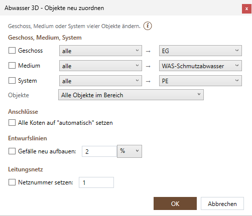
- Tools page › Reassign.
- In the dialog box check what should change. On the left it says which objects are affected ("all" or only those with this value), on the right the new value.
- Narrow down under Objects: all objects in the area, only parts (pipes, fittings, accessories) or only plumbing lines and connectors.
- Further check boxes: Set all spot elevations to "automatic", Rebuild slope (with value and unit), Set network number.
- OK, then click the objects or drag a selection window (Reassign, 2 of 2); Enter executes it – all in one step, U undoes it. Nothing selected or Esc = back to the dialog box.
A different product line takes effect for parts only at the next "Generate 3D" (the articles are different). Every field: Reassign dialog box.
Delete drainage network
Tools page › Delete drainage network: click something of the network – a part, a plumbing line or a connector. The network is highlighted; the question states how many parts, plumbing lines, connectors and markers will be deleted. Delete removes everything; U brings it back. An object without a network (no 3D generated yet) belongs to no drainage network – the command line says so.
Error markers
A marker shows where "Generate 3D" could not continue: red = error, orange = note (for example "More slope"). The result explains every marker. Fix the cause and generate the 3D again – the markers then disappear by themselves. Tools page › Error markers › Delete all only removes them from the drawing; a new "Generate 3D" places them again where the error remains.
Check 3D
Tools page › Check 3D: checks whether all 3D parts are connected without gaps and names places with more slope. The result is in the command line.
Divide objects across levels
Tools page › Divide objects across levels …: checks in all plug-ins what reaches across a dividing plane of the levels and shows it in a list to select from; "Divide" distributes the selection to the drawings of the levels. Only in a project. How dividing works: Divide across levels. For a single stack see Stack across levels.
Clashes
Tools page › Clashes section: Check looks for clashes of all 3D plug-ins – and on request with IFC building elements. Clicking a row of the list shows the place. Accepted, resolved and comments are kept at the next check; what has disappeared is resolved. You choose the rule set and the scope (this drawing only, against xrefs, also xref against xref) in the section. More under Clash detection.
CAD commands
Plumbing lines, connectors and parts follow the commands of the CAD:
| Command | What LuaCAD does afterwards |
|---|---|
| Grips, STRETCH | A plumbing line has grips at start, middle and end like a CAD line. Attached lines follow; if the network has 3D, it follows without a question by default. A stretched 3D body springs back. |
| MOVE | Like "Move"; if all 3D parts of a network move along the same way, the hidden lines and connectors come along. |
| COPY | A copy gets new identifiers. |
| ROTATE, MIRROR | Parts follow; the arrow of an in-wall carrier fixture turns along. |
| ERASE | Like Delete – with the same question. |
| Properties palette | The values are in the LuaCAD category; a change of position works like a grip. |
What happens to a network when selecting, moving and deleting with the CAD – ask, only the selected part, always the whole network, always remove the 3D parts – is a setting: gear menu › Options › Editing (default ask). If a part lies on a locked layer, LuaCAD changes nothing on it and reports it.