
Inserting openings
Choosing a template
Goal: set the type and dimensions the next opening starts with.
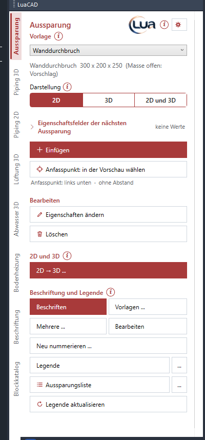
- In the palette under Template open the list and choose a template – for example "Wall opening".
- Below it you see what inserting starts with: name, type and dimensions in the units of the drawing ("Wall opening 300 x 200 x 250", for cylinders "Ø120 x 200"). "(dimensions open: proposal)" means the template leaves a dimension open and the dialog box proposes that of the type.
- The choice is remembered – also after a restart.
If there is no template yet, the line says so; Insert then places a wall opening 400 × 500 × 600. Create, change and order templates: gear menu › Manage templates … – see Managing templates. What a template contains: Template.
2D, 3D or both
Goal: choose whether a plan symbol, a solid or both is created.
- Under Display click a position – exactly one is active and highlighted in the color of the plug-in.
- The next click on Insert places:
| Position | What is created | Elevation |
|---|---|---|
| 2D (default) | the plan symbol: outline, symbol, hatch, at elevation 0 | none |
| 3D | the solid | from the clicked point or fixed with A |
| 2D and 3D | both at once, as a fixed pair | the solid with its bottom at elevation 0 |
The choice is remembered. It also affects which base points apply (2D and 3D each have their own) and – where 2D and 3D lie on top of each other – which side a click hits first when editing. What distinguishes the versions: 2D, 3D and the fixed pair.
Inserting an opening
Goal: place one or several openings in the drawing.
- Choose template and display (see above).
- Click Insert. The Dimensions dialog box opens with the values of the template ("Insert opening - <template>"). Check dimensions, clearance, type, disciplines and description. OK.
- The opening hangs at the cursor; the command line says "Wall opening insert: click the insertion point, Esc back to input" (in 2D with "(2D)", for the pair "(2D and 3D)").
- Click the point – the opening is inserted and has the next free number. The command line names it: "Opening inserted: …".
- The next identical one already hangs at the cursor. Keep clicking – or Esc or Enter: back to the dialog box, with the values just used. Enter new dimensions there and OK, or Cancel – only that ends the command.
Keys at the cursor
| Key | Effect |
|---|---|
| Space | show the base points and click one – see Choosing the base point |
| A | distance to a reference point, plus rotation and (3D only) elevation – see Inserting at a distance |
| R | rotate with the mouse; meanwhile the Space turns the 45° increment on and off, a click fixes the rotation |
| D | type the rotation angle in the command line (degrees) |
| W | pick the angle with two clicks, for example along a wall |
| ← / → | rotate by 45° (← counterclockwise) |
| Enter / Esc | back to the Dimensions dialog box |
Options
- Each inserted opening is its own undo step: U undoes the last one (for a pair both sides).
- Base point, distance and rotation stay for all rounds of the command, even when you enter new dimensions in the dialog box.
- Another button in the palette cancels inserting and starts its function – the dialog box then does not come back.
- If the drawing is not set up in mm, the command line states the units and factor the opening goes in with (see Drawing units).
- The values under Property fields of the next opening go to every new opening (2D and 3D).
The Dimensions dialog box
Goal: set dimensions, clearance, type, disciplines and description of the next opening.
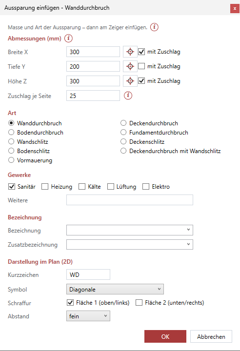
The dialog box opens before every insert; at the top there is a line with "i". It has these areas:
- Dimensions (in the units of the drawing): for a box Width X, Depth Y, Height Z; for a cylinder Radius and Length (wall) or Height (slab, floor, foundation). Next to each a crosshair button for picking and the check box with clearance. Calculating works ("250+2*25").
- Clearance per side: the space that is added on both sides of every checked dimension.
- Type: one of the types of the form (box: openings, chases, furring wall; cylinder: sleeves, core holes).
- Disciplines: check Plumbing, Heating, Cooling, Ventilation, Electrical; Other takes a free text.
- Description and Additional description: choose from the list of the template or type.
- Display in the plan (2D) – only when a 2D is created: Abbreviation, Symbol (only those that fit the form), Hatch ("hatched", or for two-part symbols "Area 1 (top/left)" and "Area 2 (bottom/right)") and Spacing of the hatch lines (fine, normal, coarse).
OK puts the opening on the cursor. The dimensions must be greater than 0, otherwise the dialog box says so. Cancel ends the command. With Tab you jump from dimension to dimension (crosshair button and check box are not in the tab order). Every field in detail: Reference › Dimensions dialog box.
Picking dimensions
Goal: take width, depth or radius directly from the plan instead of measuring them – for example the distance between the outermost pipes and the wall thickness.
- In the dialog box click the crosshair button next to the dimension. The first time, a window with a picture explains the procedure ("Pick dimensions from the drawing"); "Don't show again" hides it.
- The dialog box disappears. The command line says "Width X pick - 1 of 2: click the first point …". Click the first point (object snap helps).
- "2 of 2: click the second point" – a rubber band starts at the first point. Click the second point.
- The dialog box comes back with the new value in the field. Then the next dimension.
Width, depth and radius are measured in plan – the elevation of the points does not count, even if the points lie at different elevations. For the radius the measured distance becomes the radius: click from the center to the edge, not across the whole diameter. Height and length you pick spatially with two points or type them in the command line. If both points coincide in plan, LuaCAD asks again. Esc returns to the dialog box without a change.
Choosing the base point
Goal: hold the opening by the point that goes on the wall edge, into a corner or on an axis.
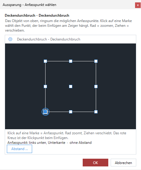
Before inserting (in the palette):
- Click Base point: choose in the preview. The dialog box shows the opening of the selected template from above, around it its base points (without and with clearance).
- Click a marker – it is the point by which the opening hangs at the cursor. Wheel = zoom, drag = pan.
- If you like, Distance …: enter X and Y to the click point, for example 50 mm from the wall – when inserting, the click is then the click point (red cross) and the opening sits next to it. No distance removes it.
- OK. Below the button you now see what applies: "Base point: bottom left corner · without distance".
While inserting (at the cursor):
- Press the Space – the markers appear on the outline, the one nearest to the cursor yellow, the one valid so far green.
- Click a marker – the opening now hangs there. A distance is kept when you change.
The base point is remembered per type and separately for 2D and 3D. Without a choice the 2D hangs by the bottom left corner without clearance, the solid by its center. Which points exist: Base point.
Inserting at a distance
Goal: place an opening at a fixed distance from a point – for example 300 mm from the corner of the room.
- While the opening hangs at the cursor, press A.
- In the Enter distance dialog box enter the amounts X and Y – in the axes of the opening. 0 and 0 = no distance.
- In the 3 × 3 field choose the base point – the side on which the distance applies follows it. The same dialog box has Rotation and (only with display 3D) Elevation.
- OK – the command line says "Now click the click point (red cross) …". Click the reference point, for example the corner of the room. The opening sits next to it.
- The distance applies to all further openings of this command; the A key button in the bar shows it. A distance from the preview (see above) works the same way.
How the distance works in all plug-ins: Inserting at a distance.
Rotating and aligning
Goal: bring the opening into the direction of the wall before placing it.
- R: rotate with the mouse, about the point where the cursor is right now. Meanwhile the Space turns the 45° increment on and off, D types the angle; a click fixes the rotation.
- D: type the rotation angle in the command line (degrees, counterclockwise); Enter without a number leaves it as it is.
- W: click two points – the direction from the first to the second is the X direction of the opening (its width). Esc = back without a change.
- ← / →: rotate on by 45°.
An opening rotates only about the vertical axis. The rotation applies to all further openings of this command. How angles work in all plug-ins: Angles.
Elevation of the 3D opening
Goal: bring the solid to the right elevation.
- Display 3D: the elevation comes from the clicked point – with object snap on a part the elevation of that part, otherwise that of the drawing plane. A fixed elevation is given with A in the Elevation field (absolute, from level or free with the mouse). Without a chosen base point the center of the solid lies at this elevation; a base point at the bottom puts the bottom there.
- Display 2D and 3D and 2D → 3D …: the solid stands with its bottom at elevation 0.
- Afterwards: move it with MOVE of GstarCAD in Z (for example
@0,0,1000). For a pair the 2D stays where it is.
Property fields of the next opening
Goal: give every new opening values right away – for example the firestop rating.
- In the palette click the heading Property fields of the next opening – the area expands (when the palette opens it is collapsed).
- Fill in the fields – by default Firestop rating (–, EI 30, EI 60, EI 90), plus your office's own fields with "ask before inserting". The description is not here but in the dialog box.
- Insert – every following opening (2D and 3D) gets these values. An empty field sets nothing.
The values stay remembered until you clear them. Which fields appear here is set by the gear menu › Property fields … (Openings tab). Openings already inserted do not change – use the Properties palette for that, see In the Properties palette.