
Quick start: the first opening
This page shows the shortest way to a wall opening – in the plan with hatch and as a 3D solid, firmly linked – and the most common changes afterwards. Every step has a picture; the details are in the linked tasks.
1. Open the palette, choose template and display
Ribbon › LuaCAD tab › Openings. The palette opens at the edge of the drawing.
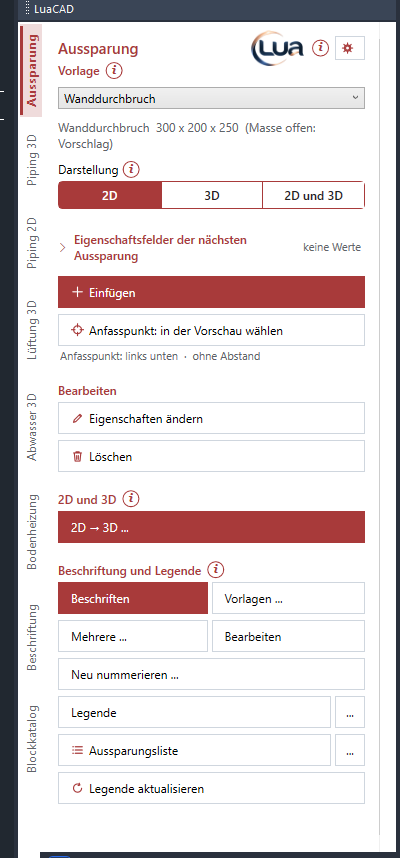
- Under Template choose "Wall opening". Below it you see the type and the dimensions inserting starts with – "(dimensions open: proposal)" means the template leaves dimensions open; you will enter them in a moment.
- Under Display choose "2D and 3D" – then the plan symbol and the solid are created together. The default is "2D".
2. Insert: enter the dimensions
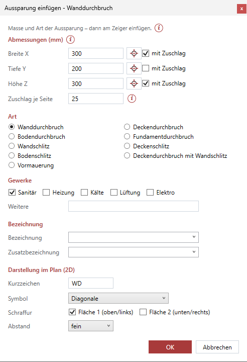
- Click Insert. The Dimensions dialog box opens with the values of the template.
- Enter the dimensions: Width X 300 (along the wall), Depth Y 200 (the wall thickness), Height Z 300. Calculating works: "250+50".
- If there should be space around the pipe: enter about 25 under Clearance per side and check with clearance at width and height – the opening then becomes 50 mm larger in each.
- Under Disciplines check who needs the opening, for example Plumbing. OK.
3. Place it at the cursor
Picture coming soonPlan view, test drawing: the wall opening hangs at the cursor by its bottom left corner (1), the wall below it (2), the action bar with Space, A, R, D, W (3)
- The opening hangs at the cursor – in the plan by its bottom left corner (without clearance).
- If the wall is at an angle: press W and click two points along the wall. Rotate at right angles with ← / → by 45°.
- Click the point on the wall edge (object snap helps). The opening is inserted and has the next free number. The next one already hangs at the cursor.
- Esc leads back to the dialog box – Cancel there ends inserting. The command line states how many openings were inserted.
4. Look at the result
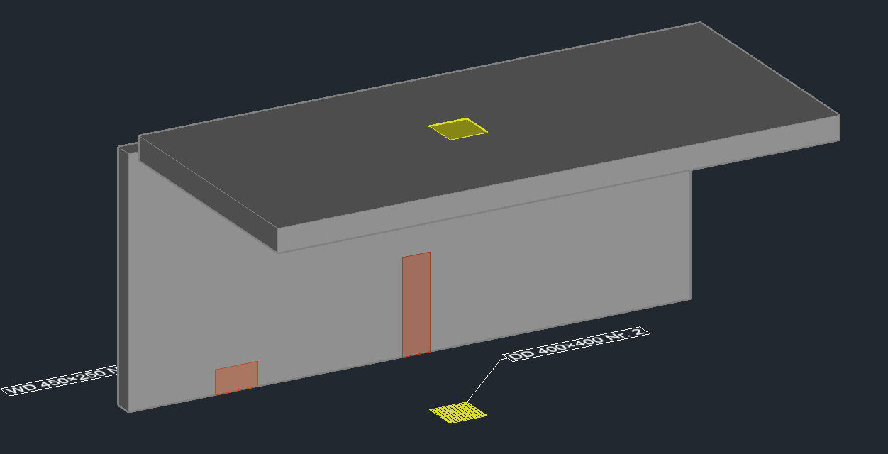
- In plan view you see the plan symbol: outline, diagonal, hatch – on the layer
LuaCAD_BAU_Aussparung_2D. - Set the view to isometric (for example with the ViewCube): the solid stands at the same place, with its bottom at elevation 0, on the layer
LuaCAD_BAU_Aussparung. - Both are a fixed pair: what you change on one side also changes on the other.
- Set the elevation of the solid with MOVE of GstarCAD in Z, for example 1000 up – the plan symbol stays where it is. See Elevation of the 3D opening.
5. Simple editing
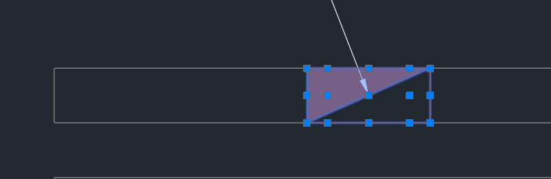
- Change dimensions or type: in the palette Change properties, click the opening, change it in the dialog box, OK.
- Drag it wider or deeper: click the plan symbol and drag a grip – the solid follows. LuaCAD does not stretch a 3D solid; it jumps back.
- Move, rotate, copy: with the commands of GstarCAD. The pair goes along; a copy gets a new number and is never linked.
- Delete: in the palette Delete or with ERASE of GstarCAD – the other side of the pair goes along, U brings both back.
What next?
Video coming soon: The first opening
- Your own templates with your usual dimensions: Managing templates.
- Color, layer and hatch by type: Display by type.
- A fixed distance from the corner of the wall: Inserting at a distance.
- Annotation, legend and schedule for the plan: Number, annotation and lists.