Highlighted buttons (in the color of the plug-in) insert something new into the drawing; all others change what is already there. Every button shows a tooltip when you hover over it. A button with a crosshair picks a value from the drawing; the calculator next to a size opens the Duct sizer.
The same key means the same thing in every plug-in. Which one applies right now is shown in the action bar; Shift and Ctrl are never used at the cursor (they belong to the CAD).
Key
Meaning in Ventilation 3D
A
before the first point: distance to a reference point; in the duct and round duct run: elevation and wall offset; in the flexible duct run: the Draw flexible duct dialog box; connected: pull away with length or distance; Move elevation: type the elevation; Move: a distance
Space
during the run: snap to angle / free; at a part: show base points; Move: free; dimension: position of the value
W
pick an angle – always two clicks
D
type an angle (degrees)
R
rotate – connected to the next arm, on a duct by a quarter or to the next side, free with the mouse
T
free at the cursor: tilt in 45° steps
F
hold at the connector or release
Z
pull away from the connector
P
during the run: match size and system of a clicked part; Move elevation: pick the elevation
N
match only the system
K
the next reducer centered, flush left, flush right
B
set or clear a reference point for typed coordinates
L / Q
Move: only along / only across
H
dragging flexible duct points: only in elevation
Backspace
flexible duct run: take back the last vertex
← / → / ↓
duct, round duct and flexible duct run: draw along the left or right side, ↓ = center; with a wall offset: switch the side; at a part: turn around
↑
duct and round duct run: new centerline; at a part: roll or switch the side
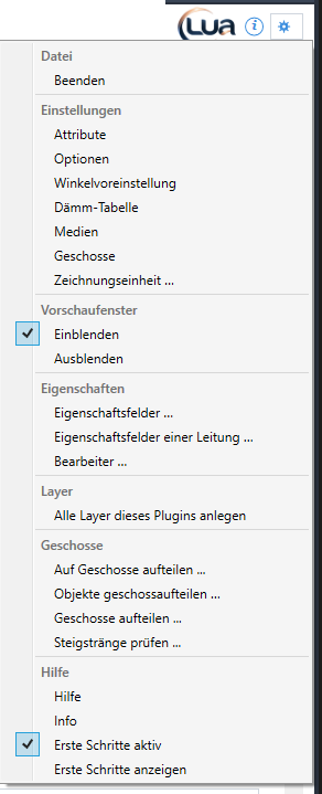
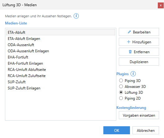
The system definitions: create and change systems, color and layer of solids, centerlines and duct accessories.
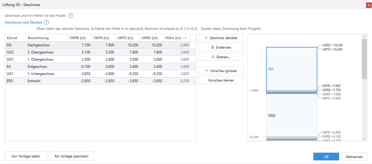
Settings › Levels
The levels of the drawing.
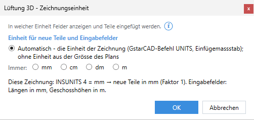
Settings › Drawing units …
In which units new parts are created and fields show lengths – for all plug-ins.
Preview window › Show, Hide
The 3D preview window of the chosen fitting (Ducts and Round ducts pages, Fitting) – Show also brings back a closed window.
Properties › Property fields …
Which fields exist (default fields, own fields) – for all plug-ins.
Properties › Property fields of a pipe …
Click a part – the fields of its network apply to each of its parts without an own entry.
Properties › Author …
The name in lists, IFC and the clash list – for all plug-ins.
Layers › Create all layers of this plug-in
Creates missing layers; existing ones stay as they are.
Levels › Divide across levels …, Divide objects across levels …
Like the buttons of the Ducts and Round ducts pages.
Levels › Divide across levels settings …
Dividing plane (TOS, BOS, FF, FC), level function on/off, question when drawing across a level boundary.
Levels › Check risers …
Checks the dividing points of divided riser ducts; the result is shown in the issues list.
Help › Help
This online help.
Help › Info
Version and program components.
Help › Getting started active
Cards of the pages and the help before inserting for this plug-in on or off.
Help › Show getting started
The tip assistant leads step by step through the shown page; all pages show their tips again afterwards.
The LuaCAD settings (for all plug-ins) are on the ribbon › LuaCAD tab › Info – see Getting started. Ventilation 3D has no system elevations and no snap radius in the gear menu: the elevation is absolute or from level, the snap radius is in the options.
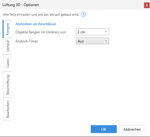
Gear menu › Settings › Options. Five tabs; OK saves all, Cancel discards.
Snap tab: Snap to objects within (1), connect timer (2)
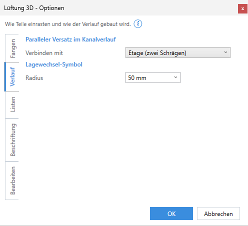
Run tab: Connect with (1), radius of the rise/drop symbol (2)
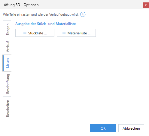
Lists tab: Parts list … (1), Bill of materials … (2)
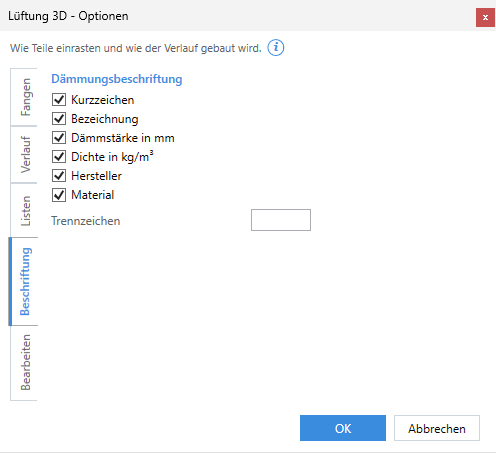
Annotation tab: the parts of the insulation annotation (1), separator (2)
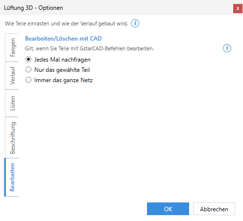
Edit tab: ask each time, only the selected part, always the whole network (1)
Tab
What it controls
Snap
How close the cursor has to come to an open connector for a part to connect, and whether it holds there by itself after a while (connect timer). The delay applies to fittings and custom parts at the cursor; ducts, branches, end caps, duct accessories and flexible ducts hold only with F.
Run
What joins two parallel offset ducts of the same size – when drawing, when connecting and when there is no room for offset elbows while moving across – and whether a circle shows the rise or drop in the plan. Applies to parts that are newly inserted or rebuilt.
Lists
Target, file name and separator of the parts list and bill of materials (the same dialog boxes as "…" on the Output page).
Annotation
What the annotation of an insulation will show. The annotation itself is not available yet.
Edit
What happens to the rest of the network when you select, move and delete with GstarCAD commands – also when deleting from the palette.
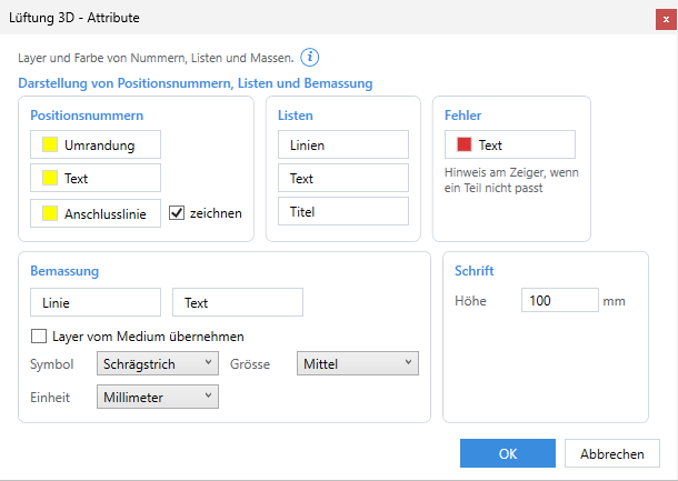
The Attributes dialog box: item numbers (1), lists (2), errors (3), dimension with symbol, size, unit (4), text (5)
Gear menu › Settings › Attributes. Each button opens layer (from the drawing), color, linetype and lineweight and shows in its color field what applies. It applies to everything inserted afterwards. The parts themselves carry the colors of their system (gear menu › Systems). Every setting: Gear menu › Attributes.
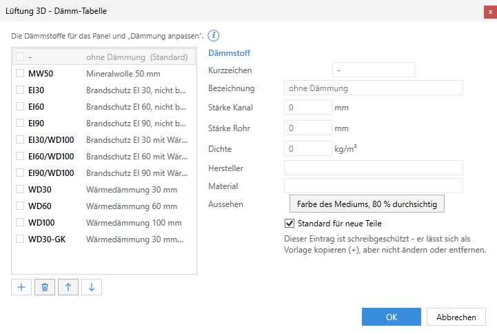
The Insulation table dialog box: the insulation materials with color field on the left (1), + / trash can / up / down (2), the values of the chosen one on the right (3), Default for new parts (4)
Gear menu › Settings › Insulation table. On the left the insulation materials (color field, short name, description), on the right the values of the chosen one. The thicknesses for duct and round duct are proposals that can be changed on the palette (whole numbers). Gray entries are fixed (for example "no insulation"): they can be copied as a template with + but not changed or removed. + creates a new insulation material based on the chosen one; the trash can removes it (parts that carry it keep their insulation), the arrows reorder the list. Every setting: Gear menu › Insulation table.
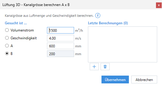
The Duct sizer dialog box: "Calculate …" (1), fields with units (2), recent calculations (3)
The calculator button next to a size row (A × B, C × D, G × H, D, D2, D3). On the left choose what is calculated (airflow, velocity, A or B, or D – the field turns gray and calculates), enter the others. By default B (rectangular) or D (round) is calculated, the velocity is set to 4.00 m/s (a usual duct velocity). Example: 1500 m³/h at 4 m/s with A = 600 gives B = 174 by calculation, rounded up to the next catalog size B = 200. The warning about the permitted velocity only appears once an airflow is entered. A calculated size is rounded up to the next catalog size (without a catalog size: rectangular 50, round 10 mm). Above the permitted velocity (up to 1000 m³/h 3 m/s, up to 2000 4, up to 4000 5, up to 10 000 6, above that 7 m/s) a warning appears. Apply writes the size to the palette; + stores a calculation (up to 20), a click in the list brings it back, the trash can removes it. See Duct sizer.
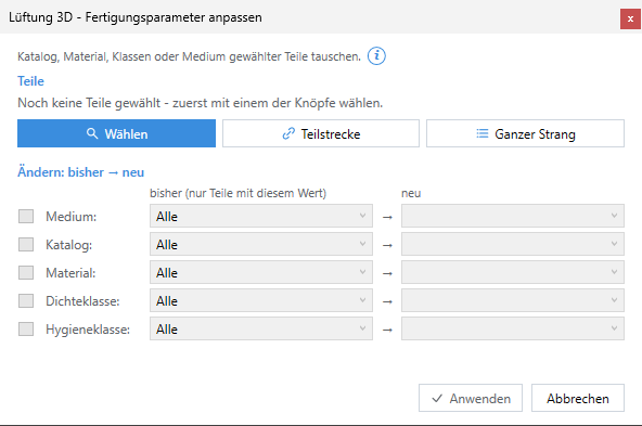
The Adjust fabrication parameters dialog box: parts (1), rows current → new (2), Apply (3)
Tools page › Fabrication parameters › Adjust. At the top Parts: how many are selected (rectangular, round, custom parts, networks) and the buttons Select, Duct section, Whole network – a button closes the dialog box, selects in the drawing and opens it again with the same entries. Below, per row (system, catalog, material, leakage class, hygiene class): check box = apply the row, current = "All" or only parts with this value, new = the new value (choosing it sets the check box). Under "new", material and classes show the values of the target catalog. At the bottom: "Affects n of m selected part(s)"; Apply only when there is something to do. See Fabrication parameters.
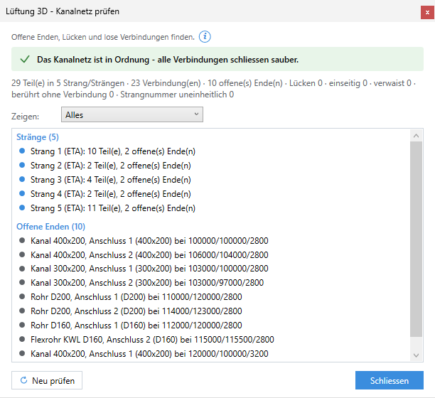
The Check duct network dialog box: verdict (1), counts (2), Show (3), list (4), Check again and Close (5)
Tools page › Check duct network. At the top the verdict (green = in order, orange = errors) and the counts; Show filters (Everything, Errors only, Networks, Open ends); a click on a row zooms there and highlights the parts; Check again after a change; Close. The findings are explained in Checking the duct network.
Query properties and click a part; the title reads fitting properties or accessory properties. The header names part, size, length and network.
Tab
Content
General
System (the crosshair takes it from another part: the dialog box closes, click a part, it comes back with all entries), insulation material and thickness (0 = none), elevation: for ducts and fittings for information (absolute and from level, with the justification) – change it with Move elevation or Change properties; for flexible ducts editable (raises or lowers the whole duct).
Dimensions
Per part type: duct and round duct size and length with With a new length, keep fixed (start V1, middle, end V2 – adjacent straight pieces in line become longer or shorter) and With the new size, keep (centerline, top edge, bottom edge; horizontal pieces only); elbow size, radius R, angle, legs E and F; reducer and transition size 1, size 2, length, offset Y and Z; offset size, length, offset; flexible duct type, diameter and length; duct accessory its values (height H, depth T, box insulation, quantity, spacing …); custom part only the file.
Connectors
Per connector (V1, V2 …) the joint type with a color mark – rectangular: (none), profile frame, M20, M30, M40, neutral; round: (none), coupling, nipple, neutral – plus size and "open" or "joined".
Size of the straight pieces and elbows: A × B or D
New size; at the edges of the selection a reducer or transition to the neighboring size is added.
With the new size, keep
Centerline (concentric), top edge or bottom edge (round duct: crown, invert) – with top/bottom edge the changed piece shifts in elevation, the neighbors stay, the transitions become one-sided. Horizontal ducts and round ducts only.
Relative elevation
More than 0 raises, less than 0 lowers the parts; adjacent straight pieces get an offset. 0 = stays.
Picture coming soonThe Draw flexible duct dialog box: elevation of the next points (1), elevation change (2), clicks lie on (3), segment length (4)
Opens in the flexible duct run with A; applies to the next points. Elevation of the next points (absolute or from level; the crosshair picks the elevation – the dialog box then comes back with all entries), elevation change (1 point – sloped to the next point; 2 points – vertical here, then horizontal), clicks lie on (left side, centerline, right side – only with a free start), segment length (fixed; empty = free). See Inserting a flexible duct.
Tools page › Insulation › Adjust. At the top Parts (Select, Duct section, Whole network, plus a system and All of this system), below New insulation: insulation material ("- stays -" or one from the insulation table with color and thicknesses) and thickness (empty = stays, or per part from the table). The line below shows the color the insulation gets (that of the material or that of the system) and how transparent it is. Apply; "Nothing to change" if neither material nor thickness is chosen. See Insulation.
Opens in the duct and round duct run with A: the elevation of the next pieces (absolute or from level, with pick) and the wall offset – the distance from the drawn line to the facing side of the duct; ← and → choose the side. The wall offset applies only to this run. See Elevation and wall offset during the run.
This section lists every setting of Ventilation 3D – on the palette, in the gear menu and in the dialog boxes – with its effect, the default value and an example. Values on the palette apply only to parts you insert afterwards and are saved right away. Settings in the gear menu apply to all drawings unless "per drawing" is stated. You type dimensions in mm; every field calculates ("600+400" becomes 1000). A "-" in the Default column means the value depends on the catalog or the data.
These rows appear on several pages (Ducts, Round ducts, Flexible ducts, Duct accessories, Products, Custom parts) but only once in the palette; justification and insulation apply per page.
Setting
What it does
Default
Example
System
The system of the next parts – sets color and layer; only the ventilation systems. The crosshair (pick values) takes system, catalog, material, insulation and size of a part. Edit systems: gear menu › Systems.
first ventilation system
supply air
Justification
What the elevation refers to: top = top edge, center = centerline, bottom = bottom edge. If the size changes along the run, this edge stays at the same height. Not on the Round ducts page.
center
top for a duct below the slab
Insulation
The insulation material from the insulation table; the thickness is proposed when choosing (duct or round duct thickness). Only where the part is insulated (flexible duct: aluminum only; duct accessories: filter, damper, sound attenuator, airflow regulator, fan, flexible duct connector).
not insulated
mineral wool 30 mm
Thickness
Insulation thickness in mm, can be overwritten; the crosshair takes material and thickness of a part.
from the material
50
Elevation change angle
Duct and round duct run only: how an elevation change is built. Auto = an offset fitting up to the duct height, otherwise the steepest angle that fits; a fixed angle = two elbows at this angle. Also applies in the middle of drawing.
Duct accessories page (filter, damper, airflow regulator, fan, sound attenuator, flexible duct connector), Products and Custom parts pages: maximum length of the transition at the first or second connector when the size does not match. The arrow swaps both.
300 / 300 mm
500 for a large size jump
Property fields of the next pipe
Ducts, Round ducts, Flexible ducts pages: fields the network of the next run receives (only what it does not carry yet).
no values
plant "AHU 01"
Show properties before inserting
Duct accessories, Products, Custom parts pages: the dialog box of the property fields before the cursor.
absolute elevation = the Z coordinate; from level = first the level, then the reference level and the value from it; free = no fixed elevation – it comes from the clicked point (object snap on an existing part takes its elevation). Switching keeps the elevation, only the number is converted. Ventilation has no system elevations.
free
from level
Level
Only with "from level": the level whose reference levels apply – preset with the level of the drawing.
level of the drawing
1st floor
Distance from
The reference level: TOS (top of slab), BOS (bottom of slab), FF (finished floor), FC (finished ceiling); its elevation in the chosen level in brackets.
–
BOS
Value
With absolute elevation the Z coordinate, from level the value from the reference level (negative = below). During a run a new number applies only after Enter or the check mark; the crosshair picks an elevation.
–
−300
Offset
Relative elevation step (negative = lower). During a run it steps by the amount at the next click at the current point (with the elevation change angle); without a run it changes the elevation by the amount. The field is empty afterwards.
EN 1505 / EN 1506 made to measure (free fabrication, any size) or a manufacturer catalog (only its sizes and fittings). Determines fittings, sizes, lengths; a change also fills elbow radius R and leg E on the palette with the catalog values.
EN 1505 / EN 1506 (made to measure)
a manufacturer catalog for spiral ducts
Material
The material of the catalog; for some manufacturers the duct fittings depend on it.
first of the catalog
galvanized sheet steel
Air leakage class
Air tightness per EN 1507 / EN 12237 (per EN 16798-3 in brackets); B is the minimum, C the recommendation. Gray = the catalog has none.
C
D for a clean room system
Hygiene class
The hygiene class of the catalog; empty is normal when the catalog has none.
first of the catalog
–
Pressure class
Made to measure only: pressure class of the system (N, M, H) – with material and largest edge it sets the sheet thickness of new parts.
M (or the default of the catalog)
H for a high-pressure system
Fixed sheet thickness
Off: sheet thickness from the table (material, pressure class, largest edge). On: the value next to it for all new parts. Goes into weight and order.
off, 0.75 mm
1.0 mm
Angle increment
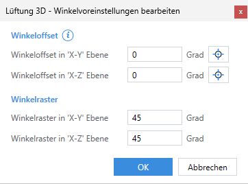
Increment of the direction while drawing (90°, 60°, 45°, 30°, 15°); the Spacebar switches it on and off at the cursor. The base direction is set under Tools › Angle.
45°
15° for fine directions
Ducts: Max. length per catalog / Max. length
Straight ducts are divided by the maximum length of the catalog or by your fixed value.
per catalog (fixed: 1000 mm)
fixed 1500 mm
Ducts: Min. length
Shortest remainder when dividing – a shorter remainder is divided together with the previous piece. Also the minimum length when dividing and with grips.
100 mm
200 mm
Reducers: Max. length per catalog / Max. length
Length of reducers from the catalog or a fixed maximum.
Draw a whole run or insert a part from the list; choosing in the list switches to Fitting.
Duct run
Fitting list
Fitting
The duct fittings of the catalog (per catalog and material).
first
Insert on its side
elbow, tee, offsets
Insert sideways instead of up or down.
off
A × B
all
Width × height; the arrow swaps, the crosshair picks, the calculator determines it from the airflow. In the made-to-measure catalog a note if it is not a preferred size per EN 1505.
While drawing and inserting, a part locks onto an open connector this close to the cursor – in cm, with "mm" at the end in millimeters; at least 16 screen pixels always apply. The circle or sphere at the cursor shows the radius.
2 cm
5 cm in a dense plan
Snap › Connect timer
If a fitting or custom part stays connected this long, it is held – as if you had pressed F (Off, 0.2 … 2.0 s).
Off
0.8 s
Run › Connect with
Two ducts of the same size, parallel and offset: offset (two slopes, the cross section stays) or offset reducer (a cone with the same inlet and outlet, one side straight).
offset (two slopes)
offset reducer
Run › Rise/drop symbol › Radius
A circle on the centerline where an elbow or tee continues vertically – shows the rise or drop in the plan plot. Radius in mm; Off = no symbol.
50 mm
80 mm
Lists › Parts list …, Bill of materials …
The options of the list output (drawing or file, file name, separator, text height, per system).
default template
bill of materials as an Excel file
Annotation › short name, description, insulation thickness in mm, density in kg/m³, manufacturer, material
What the insulation annotation will show.
all on
only short name and thickness
Annotation › Separator
Stands between the values, for example " / " or ", "; empty = space.
empty
", "
Edit › Edit/delete with CAD
Ask each time (a question shows the options, "Remember answer" then always applies), Only the selected part (the neighbors stay), Always the whole network (selecting a part means selecting, moving or deleting the whole network). Also applies when deleting from the palette.
Color and transparency of the insulation solid (white or black = color of the system; 80 % transparent if not set).
light gray, 70 %
Default for new parts
Marks the default of the table (shown as "(default)" in the list). If the palette has not stored an insulation yet, this material is preselected – with its thickness. Example: mark "MW50" (mineral wool 50 mm) as default – a new duct is then insulated with 50 mm until you choose something else on the palette.
not insulated
+, trash can, arrows
New (copy of the chosen one), remove, order. Fixed entries are gray.
The system definitions for ventilation: create, duplicate, rename systems and set their look per entry – solid (ducts, round ducts, fittings, with transparency, also the preview at the cursor), duct centerline, round duct centerline, duct accessories. The insulation has its color in the insulation table. A "by layer" change goes to the layer of the current drawing.
Levels
Per level the short name, the description and the elevations of the reference levels TOS, FF, FC, BOS. A change never moves a part. See Elevations and references.
Drawing units …
In which units new parts enter the drawing and fields show lengths: automatic, mm, cm, dm, m. Applies to all plug-ins – see Drawing units.
#Gear menu › Properties, layers, levels, preview window, help
Entry
What it controls
Preview window › Show, Hide
Whether the 3D preview window stands next to the palette; it appears only on the Ducts and Round ducts pages with "Fitting". Display, view direction and base point are set in the window itself.
Property fields …
Which fields exist (default fields on/off, own fields) – for all plug-ins.
Property fields of a pipe …
Click a part: the fields of its network (plant, status …).
Author …
The name in lists, IFC and the clash list – for all plug-ins, empty by default.
Layers › Create all layers of this plug-in
Creates missing layers (for example for an office template); existing ones stay as they are. You change names, colors and linetypes in the GstarCAD layer manager – the assignment stays.
Levels › Divide across levels settings …
Dividing plane, level function on/off, question when drawing across a level boundary (ask, always, never).
Help › Getting started active
Cards of the pages and the help before inserting for this plug-in on or off.