
Drawing pipes
Inserting a pipe
Goal: click a single-line pipe point by point into the plan – with the system, system elevation and size of the palette.
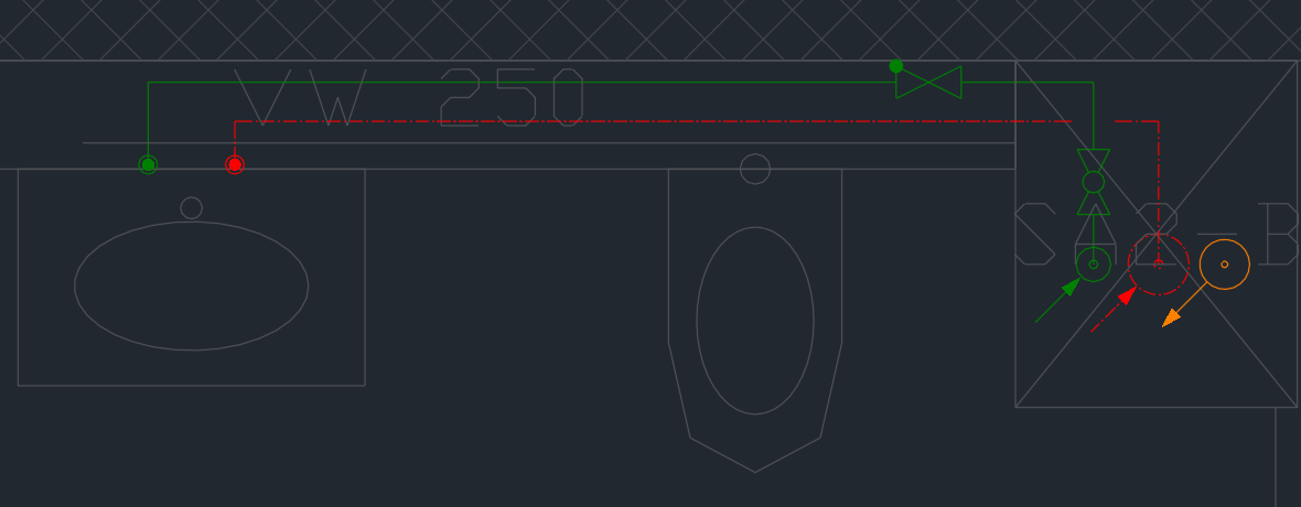
- Pipe page: set system, system elevation, size, flexible and angle increment, then click Insert pipe. Before the first point the insertion help appears with a picture.
- Click the start (1): free, at a pipe end (the run continues there), in the middle of a pipe of the same system (a tee is created there) or at a connector (the pipe takes its system, see Connector).
- Click further points (2, 3). A number you type is the length of the next segment in the direction of the cursor. A click in the middle of another pipe of the same system breaks it, and the tee is placed there; if the other pipe ends freely at that point, it is trimmed back and a corner is created.
- If the segment ends at a connector of a 2D fixture or manifold, the run ends there.
- Enter or Esc ends the run – the placed segments stay, only the segment at the cursor is dropped. Each segment is its own undo step.
Keys at the cursor
| Key | Effect |
|---|---|
| A | before the first point: distance to a reference point (see below); while drawing: system elevation, wall offset and fixed length in one dialog box (see below) |
| Space | snap to angle (angle increment of the palette) or free – the bar names what applies next |
| W | pick the base direction of the angle increment with two clicks (for example along a slanted wall) |
| D | type the base direction of the angle increment (degrees) |
| P | the next click takes all values of a pipe into the palette (places nothing) |
| N | the next click takes the system only |
| ← / → | only with a wall offset: put the pipe on the other side of the drawn line |
The circle at the cursor shows the snap radius: when it touches a pipe of the same system, the run snaps to it. A pipe of another system does not snap. Set the size in the gear menu › Snap radius when drawing ….
Before the first point: distance to a reference point
Goal: start a pipe exactly at a distance from a wall corner or column.
- After Insert pipe, before the first click, press A.
- In the Distance dialog box enter the values X and Y.
- Click the reference point, for example the wall corner (the red cross shows it, object snap helps). The pipe starts at the entered distance from it.
- Then the run continues as usual.
More about distances in all plug-ins: Inserting at a distance.
System elevation, wall offset and fixed length while drawing
Goal: change the system elevation during the run, keep the pipe at a fixed distance from a wall, or place a segment with an exact length.
- While drawing press A – the dialog box System elevation and wall offset while drawing opens.
- System elevation: choose another one. It applies from the next click; an elevation change circle is created at the corner – the upper pipe runs to the center of the circle, the lower one ends at its edge. The new system elevation then also shows in the palette.
- Wall offset: the distance from the drawn line (the wall) to the pipe, and the side. The wall offset applies only to this run; ← and → then switch the side. Two segments with a wall offset meet mitered; after switching the side a cross piece joins them.
- Fixed length: 0 = drag with the mouse; otherwise after OK a segment of this length is inserted in the current direction.
- Click OK and continue clicking.
Matching the properties of a pipe
Goal: draw the next pipe with exactly the values of an existing one, without typing them.
- While drawing press P (or click the toggle button in the bar – it stays highlighted until you click).
- Click an existing pipe. System, system elevation, size, flexible and radius go into the palette; nothing is placed.
- Continue clicking – the next segment has the new values.
N takes only the system in the same way. Without a running command the Pick buttons next to "System" and "System elevation" in the palette do this.
Inserting parallel pipes
Goal: insert several pipes side by side at once – for example cold water, hot water and recirculation – from the riser template chosen last.
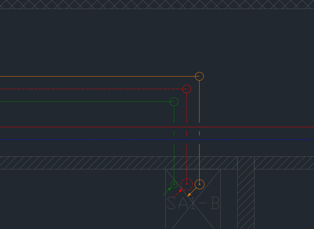
- Choose the riser template on the Risers/connectors page (the line "With template: …" tells you which one applies) and set the system elevation – risers have none, the pipes take the one of the palette.
- Click Insert parallel pipes (Pipe or Risers/connectors page). With Show the dialog box before inserting checked (default) you first check or change the risers – this applies to this insertion only.
- Click the start: at risers or at existing parallel pipes each pipe starts at the one of its system, at a manifold at its outlet; otherwise free.
- Click point by point. Corners are mitered, flexible pipes run concentrically.
- If the run ends on existing parallel pipes, each pipe connects to the pipe of its system (tee, corner or continuation); at risers each pipe ends at the riser of its system.
- Enter = finish. With the dialog box shown first, it comes back afterwards with your entries; only Cancel in the dialog box ends the command.
Keys at the cursor
| Key | Effect |
|---|---|
| P | before the first point: pick pipes (see below) |
| A | before the first point: distance to a reference point; while drawing: system elevation, wall offset and fixed length |
| Space | snap to angle / free |
| S | put the risers on the other side of the drawn line |
| W / D | pick or type the base direction of the angle increment |
Picking pipes
Goal: continue parallel pipes with the systems, sizes and spacings of pipes already drawn.
- Insert parallel pipes, before the first point P (pick pipes).
- Drag a selection window over drawn parallel pipes.
- Their pipes become the template for this run – the stored riser template stays as it is. The command line names the number of risers.
- Click the riser or the location where the new parallel pipes start and continue.
Flexible
Goal: draw bendable pipes (PEX, multilayer pipe from the coil) with rounded corners.
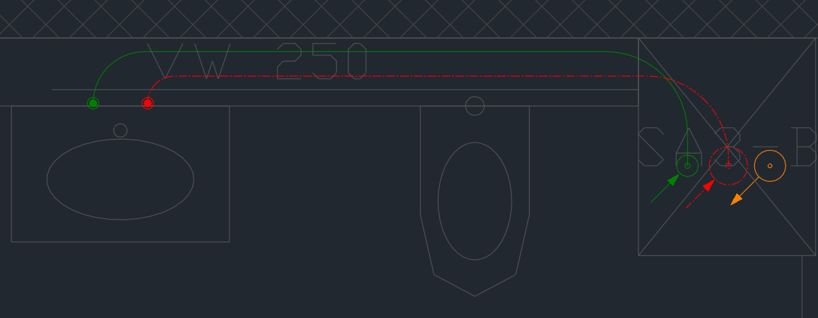
- Pipe page: check flexible (rounded corners) and enter the radius (default 300 mm).
- Click Insert pipe or Insert parallel pipes and click as usual. At the cursor you see the rounding as it will be created after the click.
- If the radius does not fit at a corner (the segments are too short), a smaller radius is used; the corner is red at the cursor and the command line names both radii.
Every corner between two flexible pipes on the same system elevation is rounded; in parallel pipes the arcs run concentrically. You make an existing pipe flexible or rigid with Properties – it becomes a polyline or a line again, its data stay.
Connecting two pipes
Goal: connect two pipes with each other – Piping 2D calculates the routes and shows all proposals at the cursor.
- In the tools at the bottom click Connect. Before the first click the insertion help explains the procedure.
- Click the first pipe (1). Several pipes at once: click next to them and drag a selection window.
- Click the second pipe (2). In the middle of a pipe a tee is created, near its end a corner.
- The proposals appear in color (3) – those without shortening first. Tab or right/left arrow switches, the yellow one is selected; a click or Enter accepts, Esc discards.
- Then the next pair right away; Enter = finish. Each joint is its own undo step.
The new segments have the values of the pipe clicked first. If the second pipe is on another system elevation, an elevation change circle is created at the target.
Options
| Case | What happens |
|---|---|
| Two systems (supply and return) clicked one by one | They are joined; the connecting piece carries the system of the pipe clicked first, the second pipe is broken with its own system |
| Several pipes (selection window) | one pair finds the route, the others run along parallel and offset; per system only |
| Pipe end at a riser, symbol, connector or elevation change | this end is not open – a tee is always created |
| Flexible pipes | the shortest leg is at least the radius |
Joining two pipes into one
Goal: join two pipes whose ends meet – for example after Break – into one pipe again.
- Click Connect and click both pipes.
- If their ends meet and they have the same values (system, system elevation, size, flexible and radius), they become one pipe: in one line a single line, otherwise around the corner.
- If the values differ, everything stays as it is; the command line names the difference.
Property fields of the next pipe
Goal: give every new pipe its property fields right away – for example plant or construction phase.
- Pipe page, at the bottom the area Property fields of the next pipe: expand it and enter the values.
- Click Insert pipe or Insert parallel pipes. Every new pipe receives the entered fields – only those it does not carry yet.
- Later you change the values of a pipe in the GstarCAD Properties palette.
Which fields exist is set in the gear menu › Property fields … (for all plug-ins); the fields of the network of a pipe are shown by the gear menu › Property fields of a pipe ….