
Fabrication
The Fabrication page adds to pipes that already have 3D what the shop and the installers need. Much of it mainly concerns the process piping catalog; isometric, flow direction and PCF work for every catalog.
Extruded outlet
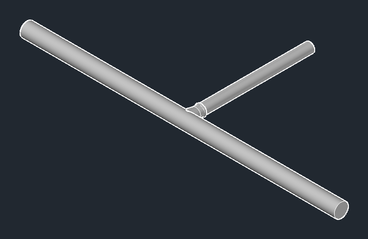
Goal: take a branch straight out of the pipe instead of using a tee – the main pipe runs through as one pipe.
- Extruded outlet › Create and click the pipe.
- Choose the outlet in the dialog box – the list shows only outlets that fit this pipe.
- Slide the outlet along the pipe and click. On the command line "Rotate" turns it by another 45 degrees, "Angle" takes a typed angle. Esc = cancel.
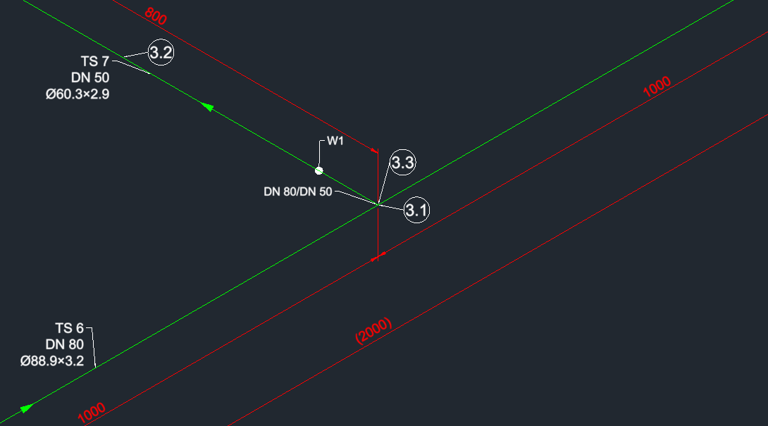
Example: A cold water pipe DN 80 in the process piping catalog (pipe class CS01), 2 m long, has a DN 50 branch of 800 mm in the middle. "Generate 3D" places a reducing tee there according to the branch table. With Change branch, a click on the branch and the choice Extruded outlet it becomes an extruded outlet: the DN 80 main pipe runs through as one pipe – one item number (3.3) and one dimension (2000) in the isometric –, the DN 50 outlet is welded to the extruded outlet (one weld W1 instead of three at the tee).
Welds
Goal: place, change and delete welds between welded parts.
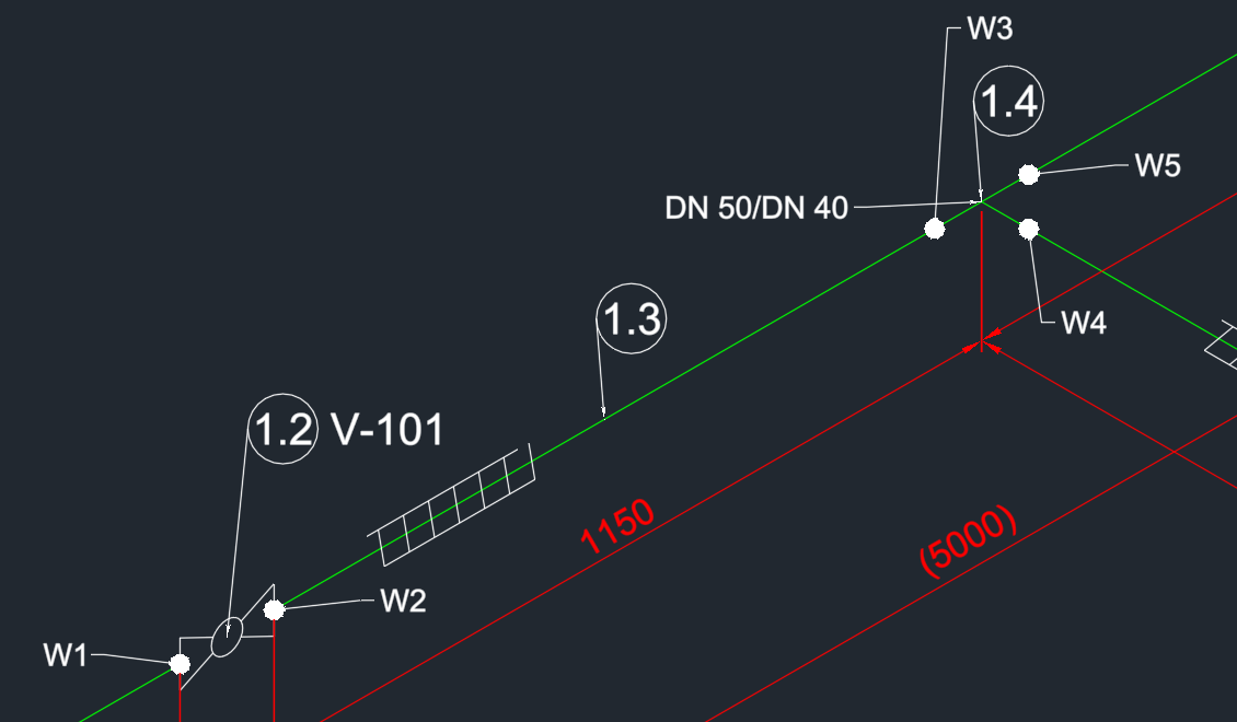
| Short | Weld | Meaning |
|---|---|---|
| SW | shop weld | welded during prefabrication |
| FW | field weld | welded on site |
| FFW | field fit weld | on site: the pipe is cut to size and gets an allowance |
- Welds › Create: click a part and its counterpart = one weld; Enter instead of the counterpart = all welds of the part; click into empty space = selection window over several joints.
- Change: select welds and set process, location (shop/field) and procedure in the dialog box; "unchanged" leaves the value of each weld as it is. A field weld divides the pipe into prefabricated sections (spools).
- Delete removes welds you click one by one, Delete all removes all welds of the drawing (after confirmation).
- Settings: defaults for new welds and the size of the weld bodies (100 = as large as the pipe).
Flanges
Goal: add flange, gasket, mating flange and bolts at a free end.
- Flanges › Create automatically and click a free end.
- In the dialog box choose the type and the pressure rating (PN) and whether the flange at the pipe end, a gasket in between, the bolt set and collar sleeves come along.
- OK – the parts are added.
Example: The DN 50 pipe ends at a pump with a flanged nozzle. Click the free end, choose PN 16 and check gasket, mating flange and bolts: the pipe end then carries flange, gasket, mating flange and bolts, ready for connecting the pump.
Bolt sets
- Bolt sets › Create and click a flange: bolts (and, with Collar sleeves checked, sleeves too) to the opposite flange.
- Delete and click a bolt: all bolts and sleeves of the pair are removed.
Example: Two flanges were placed without bolts (check box "bolt set" off). Bolt sets › Create and click one of the two flanges – the bolts of the pair are then placed between both flanges.
Flow direction
Goal: define where the fluid flows – the isometric draws the flow arrow only when the direction is defined.
- Define flow direction and click a pipe.
- Choose the direction at the cursor and click.
- It applies to all connected pipes of the same system: distributing, into both outlets at every tee; collecting, all inlets into one outlet.
Remove flow direction takes the definition away again. If it is missing, the isometric asks for it.
Isometric
Goal: output a pipe network as an isometric drawing with dimensions, item numbers, welds, parts list and title block.
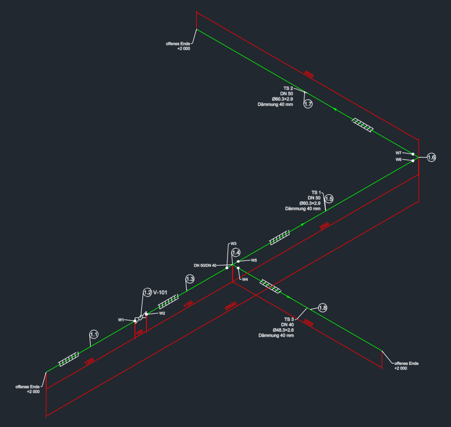
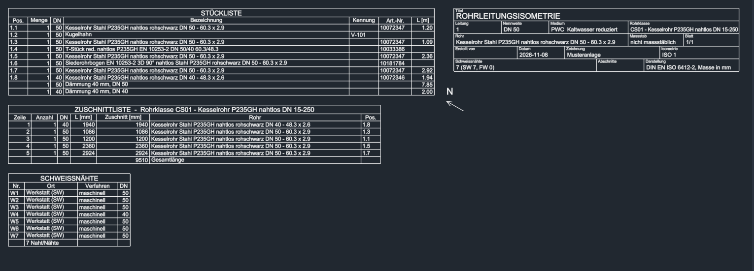
- Create isometric and click a pipe.
- Choose a place in the drawing: the network of the pipe is inserted as an isometric. Without a defined flow direction LuaCAD asks for it first.
- Each dimension and each label can be moved separately (Ctrl + click selects a single one).
- Remove isometric and click one of its elements: the whole isometric including its sheet is removed.
Options sets how each new isometric looks: scale and text, dimensions (true lengths, overall dimensions, dimensions to field welds), sloped runs and slope, labels (nominal sizes, spot elevations, item numbers, flow direction, description at valves), welds and weld numbers, colors and the sheet with lists, title block and north arrow. Existing isometrics stay as they are – create them again to see changes.
The lists on the sheet
With the sheet (Options › Sheet) the title block and the lists stand next to the isometric – in the example the cold water pipe DN 50 with ball valve V-101, reducing tee to the DN 40 branch and one elbow.
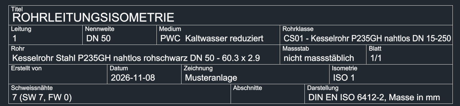
LuaCAD fills the title block from the pipe; "Created by" is the name from gear menu › Properties › Editor (empty = empty).
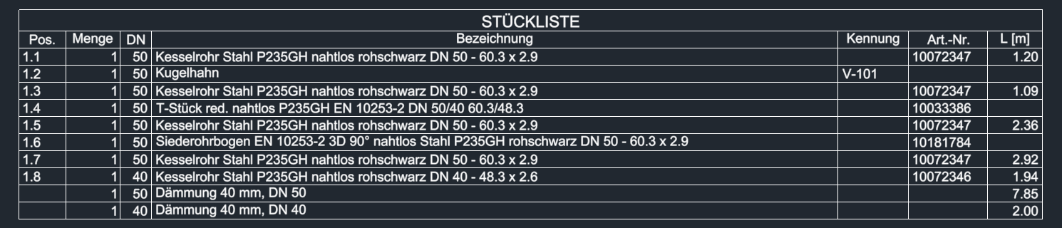
The parts list counts each part with its item number; pipes are listed with their length in meters, the insulation as a total per nominal size.

The cut list is the work list of the shop: each straight pipe cut to length, sorted by nominal size, with a reference to the item.
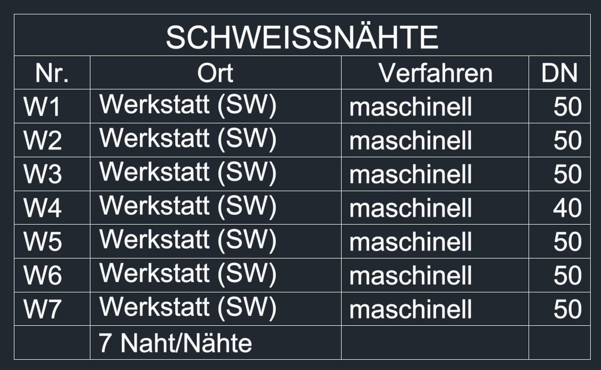
The welds list names each weld of the isometric: shop welds (SW) are made during prefabrication, field welds (FW) during installation – you change a weld under Welds.
Joints without a weld
If the pipe already has welds, but not at every welded joint, Create isometric asks before drawing:
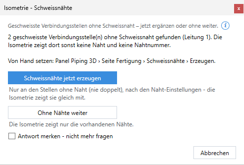
- Create welds now adds a weld only at the joints without one (never a second one at the same place), according to the weld settings; the isometric shows them right away. U undoes welds and isometric together.
- Continue without welds draws the isometric with the existing welds only.
- Cancel creates no isometric.
- You set welds by hand with Welds › Create on this page.
- Remember answer - do not ask again: from then on the chosen answer always applies; turn it on again in the LuaCAD settings › Notes and questions.
Spools
Goal: divide the pipe into pieces that are welded in the shop and delivered in one piece.
- First open Spool settings and turn spools on (the maximum size is set there too).
- Number spools and click a pipe: each part gets its spool number (for example Line-S1, -S2 in flow direction). If a spool is larger than the maximum size, LuaCAD suggests welds where it can be divided.
- Spool isometrics inserts one isometric with lists per spool.
- Spool number by hand overrides the number of a part.
The limits of a spool follow by themselves: at every field weld and field fit weld, at flange pairs, flanged valves and unions. You set a limit yourself by changing a weld to field with Welds › Change.
Example: In the pipe from the isometric picture the weld W5 at the tee is changed to field with Welds › Change. Number spools divides the pipe there: everything before W5 with the tee and the branch is spool S1, the pipe from W5 with the elbow is spool S2 – both come welded from the shop, W5 is welded on site.
PCF export
Goal: output pipes for stress analysis and pipe fabrication programs.
- PCF export and click the pipes; Enter.
- Choose a folder: one PCF file per pipe is created (in mm).
The drawing stays unchanged. Each joint gets its end type (flange, weld, thread, push-fit); valves carry their tag.
Example: For the pipe from the isometric picture one file is created with pipes, elbow, tee and the ball valve: the ball valve is in it with the tag V-101 and welded ends, the pipe fabrication program reads cuts and welds from it.