
Piping 3D step by step
The workflow
Goal: plan a cold and hot water distribution in the basement corridor of the sample project and then change it the way it happens every day.
The example is the basement of the sample project, the plumbing drawing of level UG1: the distribution pipes run in the corridor along the corridor wall, a branch line leads through the corridor wall into shaft SA1-B, where the risers go up. Drawing is quick - this page focuses on editing:
- Draw the distribution pipes in the corridor
- Insert the risers in the shaft
- Connect riser and distribution pipe - tee instead of trimming
- Generate 3D
- Change the nominal size - and generate 3D again
- Change the elevation of a pipe
- Insert a ball valve in-line
- Read the issues
- Move, break, join
- Annotation, item numbers and list
1. Draw the distribution pipes in the corridor
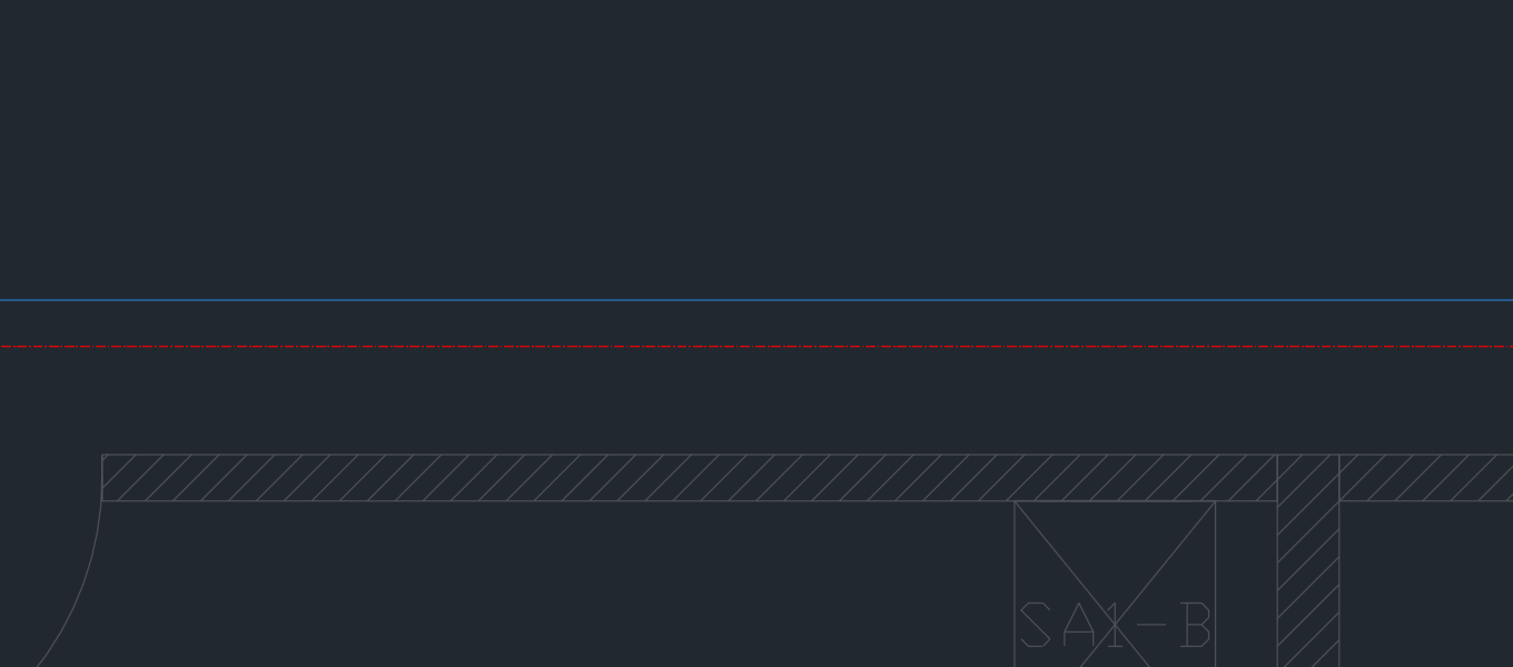
- Page Pipe: system cold water (PWC), stainless steel press system, DN 32, system elevation or fixed height 2450 mm above the floor (in the basement Z = -550).
- Click Insert pipe, start at the left end of the corridor, press A and enter the distance to the corridor wall (here 490 mm), draw along the corridor, Enter.
- Do the same for hot water "PWH" (DN 32), 150 mm closer to the wall and 150 mm higher.
At first only the routing lines are drawn - thin lines in the color of the system. Pipes and fittings are created by Generate 3D (step 4). Details: Insert pipe.
Keys at the cursor
| Key | Effect |
|---|---|
| A | elevation and wall offset while drawing |
| Space | snap to angle / free |
| Enter | end the run |
2. Insert the risers in the shaft
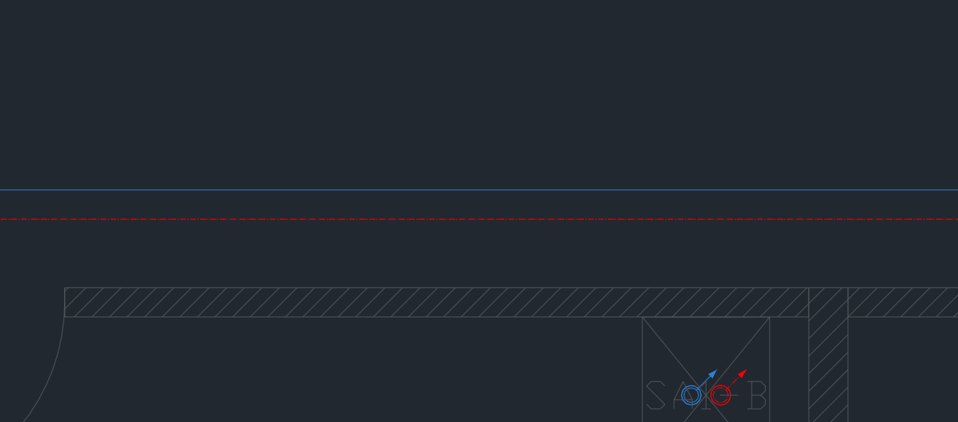
- Page Risers/connectors: choose the riser template in the list (here a template with a cold and a hot water riser DN 32, 150 mm apart - you create a template once in the Riser templates dialog).
- Click Insert risers/connectors. In the dialog confirm the direction "up" and the target (here the next level).
- The risers hang at the cursor. Space switches the riser you hold; click in the middle of the shaft.
If you are asked "Riser across levels": "Not now" keeps the riser in this drawing; you can divide it later (Divide across levels).
3. Connect riser and distribution pipe
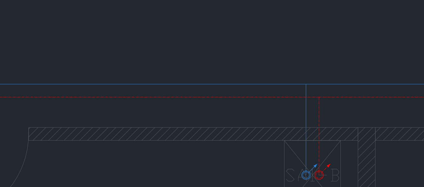
- Page Tools > Connect.
- Click the riser first in the shaft, then the distribution pipe along its run (not at its end).
- LuaCAD shows the solutions in color; the yellow one is selected. Tab pages through, Enter or a click accepts.
4. Generate 3D
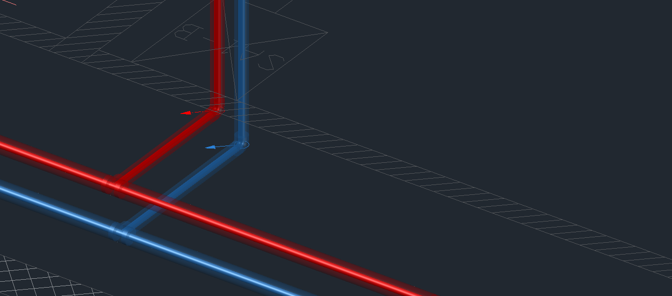
- Page Tools > Generate 3D and click a pipe - or Enter for all.
- LuaCAD places pipes (in bar lengths with press couplings), tees, elbows and reducers from the catalog of the pipe and numbers the parts per riser.
More: Generate 3D, Pipe lengths.
5. Change the nominal size
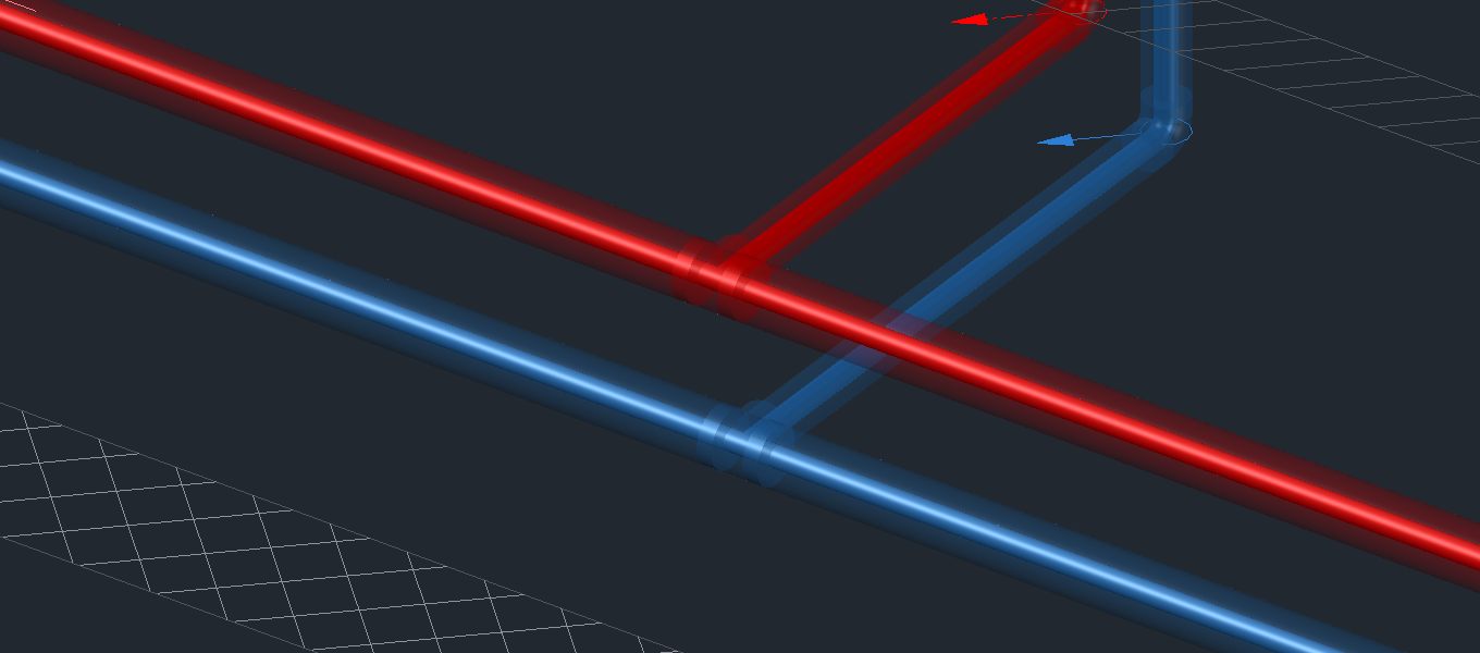
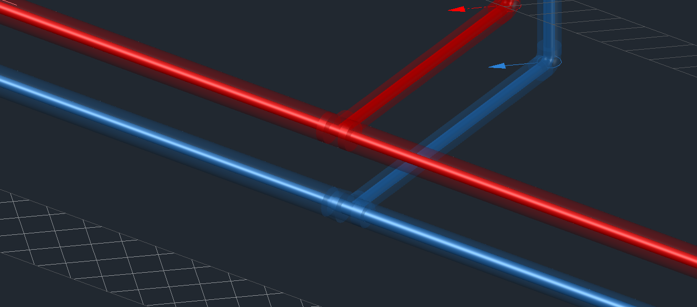
The supply from the house connector to the branch shall be DN 40:
- Footer Properties (or page Tools), click the cold water pipe left of the branch, Enter.
- In the Properties dialog set only DN to 40 and check it - the other values stay as they are. OK.
- LuaCAD removes the 3D of the riser network (message "3D removed - the routing lines are visible again"). Run Generate 3D again: the branch now has a tee 42 x 35 x 42 with a reducer to DN 32.
6. Change the elevation of a pipe
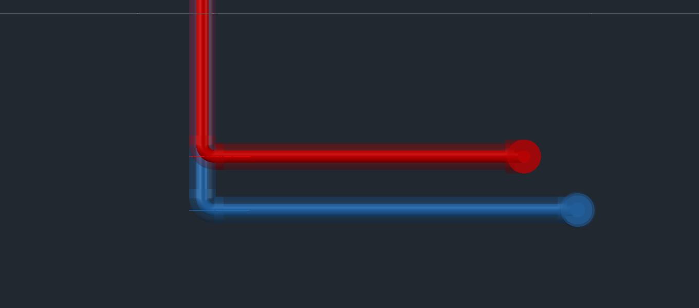
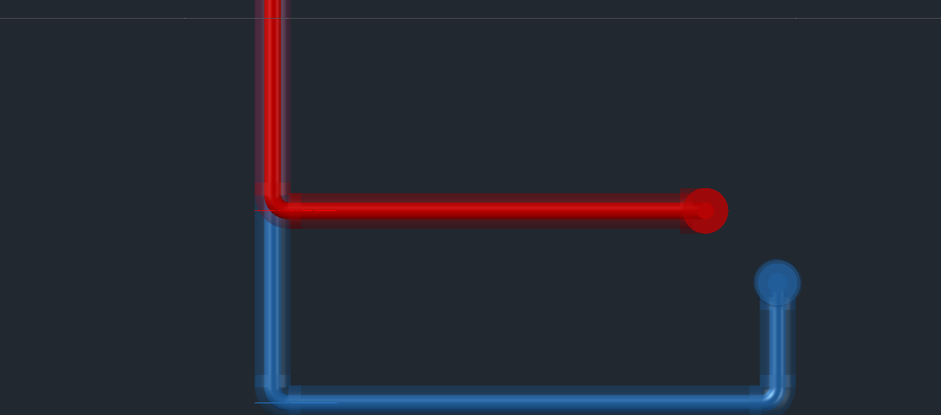
The cold water branch line has to pass below an obstacle, 250 mm lower:
- Page Tools > Change elevation, click the branch line, Enter.
- In the Elevation dialog enter the new elevation (absolute -800 mm or from the level).
- Generate 3D.
7. Insert a ball valve in-line
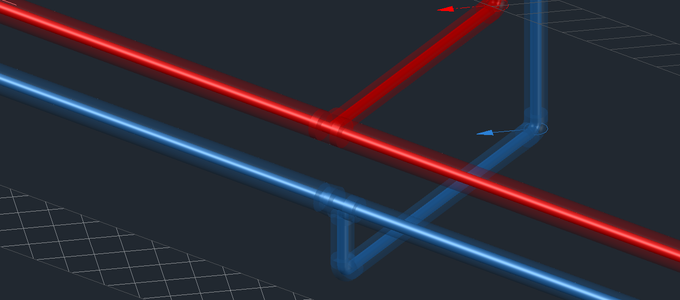
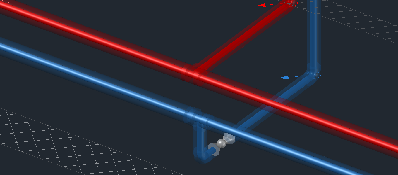
Every riser needs a shut-off:
- Page Symbols: choose "Ball valve", Insert.
- Click the branch line - the ball valve is inserted in-line and slides along the pipe; click at the position you want.
- LuaCAD cuts the pipe, places the valve with the DN of the pipe and regenerates only the area next to it.
With a tag in the Valve dialog the valve appears in lists and in the isometric. More: Insert in-line.
8. Read the issues
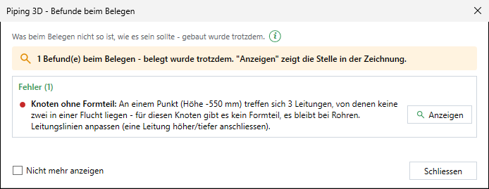
What is not as it should be when generating 3D is built anyway - and listed bottom right in the issues list. Show zooms to the position.
9. Move, break, join
- Move (page Tools): select pipes, move them with the cursor or by a distance with A. Connected pipes are extended or shortened. Select all pieces of a run (window) - if only one piece of a continuous pipe is moved, an offset appears at the branch. Details: Move, Grips, Stretch.
- Break: break a pipe at a point into two pipes, for example to change only one part. The break point stays (also with Generate 3D) until you remove it with Join. Details: Break.
- Pipe variant: if the catalog offers several versions of elbows or tees, the palette shows the rows Pipe variant, Elbows and Tees; the pipe carries the version, Generate 3D uses it without asking. Details: Insert pipe.
10. Annotation, item numbers and list
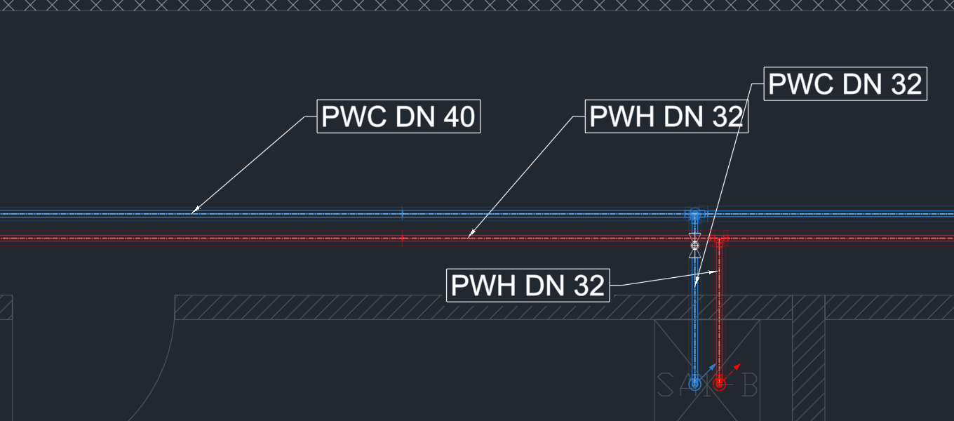
- Page Output > Annotate: choose the template for system and DN, click the pipe, place the text.
- With Multiple you annotate all pipes at once - with the filter Length (for example 800 mm) short pieces at the fittings stay without text.
- Item numbers are created automatically per riser network when you generate 3D (1.1, 1.2 ...); make them visible with the item number template with DN.
- Bill of materials: combined by article, pipes with length - for example "stainless steel pipe 42 mm, 7.8 m". The table hangs at the cursor and is placed next to the plan.
More: Annotate, Item numbers, Bill of materials.