
Drawing units and display units
All plug-ins calculate, store and compare internally in millimeters. Units matter in only two places:
- Drawing units – the size at which new parts come into the drawing. In a drawing in meters, a pipe of 3000 mm comes in as 3 units.
- Display units – the unit in which the input fields show lengths, distances and elevations. They follow the drawing units: in a drawing in meters the field shows 2.4 instead of 2400.
Both follow one default for all plug-ins and all drawings.
Choosing the drawing units
Goal: set the units in which the plug-ins insert new parts and the fields show dimensions.
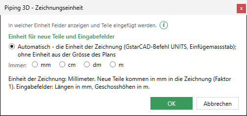
- Open the dialog box: ribbon › LuaCAD tab › Info ribbon panel › LuaCAD settings › Drawing units … – or in the gear menu of a plug-in (Piping 3D: gear menu › Settings › Drawing units …). It is the same dialog box.
- Choose Automatic (each drawing brings its own units) or Always: mm, cm, dm or m (these units for every drawing).
- The line below tells you what the choice means for the open drawing: where the units come from, the factor for new parts, and the units of lengths and floor-to-floor heights in the fields. Example in a drawing in millimeters: "Units of the drawing: millimeters. New parts go into the drawing in mm (factor 1). Fields: lengths in mm, floor-to-floor heights in m." If the drawing has no units, the line says what LuaCAD recognizes from the size of the plan ("The drawing has no units – recognized from the size of the plan: meters") or only suggests (then the command line asks once at the first insert).
- OK – the choice applies at once in all plug-ins. Open palettes switch their fields; the value stays, only the number is converted.
| Choice | What happens |
|---|---|
| Automatic | Each drawing sets its own units – through its units in GstarCAD (UNITS command, "insertion scale"). If it has none, LuaCAD estimates them from the size of the plan (see below). |
| Always: mm, cm, dm, m | These units for every drawing, whatever the drawing says. Useful when plans arrive without units or with wrong ones. |
Where "Automatic" takes the units from:
- If the drawing has units (mm, cm, dm, m), they apply.
- Units LuaCAD does not know (kilometers, yards, micrometers …) count as mm; the command line says so once per drawing.
- Without units, LuaCAD estimates from the longer side of the plan: under 400 units = meters, over 20,000 = millimeters. In between it is uncertain (a building in cm or a detail in mm) – at the first insertion the command line asks once in which unit the drawing was drawn, with Mm, Cm, Dm, M. The answer is written into the drawing as its units – nobody asks again. Esc keeps the suggestion (up to 4000 units cm, otherwise mm) for this session.
- An empty drawing without units counts as mm.
How fields show dimensions
Every field shows its unit next to it. Which unit depends on the kind of value:
| Kind of value | mm drawing | cm drawing | m drawing | Example |
|---|---|---|---|---|
| Lengths, distances, elevations | mm | cm | m | elevation 2400 mm shows as 240 (cm) or 2.4 (m) |
| Floor-to-floor heights, level elevations | m | cm | m | floor-to-floor height 3 m shows as 3.000 or 300.0 (cm) |
| Nominal size (DN), insulation thickness, ventilation duct and pipe sizes, size in Piping 2D | always mm | always mm | always mm | DN 20, insulation 20 mm, duct 400 × 200 |
| Slope | % | % | % | 1.5 % |
| Angle, rotation | ° | ° | ° | 45° |
- Decimal places: as many as needed to keep a hundredth of a millimeter – mm up to 2, cm up to 3, dm up to 4, m up to 5; only the necessary ones are shown ("250 mm" → "25" in cm, "0.25" in m). Floor-to-floor heights have fixed places (m 0.000, cm 0.0).
- Suffix: a unit at the end always takes precedence over the display units: "1.2m", "250cm", "80mm". In a mm drawing "1.2m" gives 1200.
- Switching: when another drawing becomes active, its units change or the default changes, the fields convert – the stored value stays.
- A dialog box that opens during a command (Type a distance, elevation while drawing) shows the unit with which this command inserts and no longer switches.
Calculating in fields
You may type a calculation in any number or dimension field; when you leave the field, the result appears.
| Character | Meaning | Example |
|---|---|---|
+ - | plus, minus | "600+400" → 1000 |
* x | times | "2*450" → 900 |
/ : | divided by | "3000/4" → 750 |
( ) | parentheses | "(1200-2*50)/2" → 550 |
Comma and period both count as the decimal separator. A suffix goes at the end of the whole calculation: "600+400mm". Fields for names, abbreviations and article numbers do not calculate – "12-34" stays as it is.
Values in the command line
What you type in the command line – coordinates, points, a length at the cursor – applies in drawing units, as with every GstarCAD command, not in the display units of a field. In a drawing in meters "@3,0" is 3 m to the right, in a drawing in mm it is 3 mm.
If the drawing is not in mm, the command line names the units and the factor once per drawing at the first insertion: "Drawing in m: dimensions are in m, parts come into the drawing with factor 0.001."
The project units
In a project the drawings are attached to each other as xrefs without a scale – that is only right when all have the same units. So every project has one unit:
- You choose it in the project wizard, step Project, field Project units: Take over (from the first drawing that is aligned) or fixed millimeters, centimeters, meters.
- LuaCAD brings every project drawing into these units: the content is converted about the origin at true size, the units of the drawing and the linetype scale follow. This happens after creating the project, after alignment, after adding a discipline or level, and after replacing an IFC.
- A drawing still waiting for alignment gets its units when it is aligned.
- With "Automatic", the plug-ins thus insert in the project units in any project drawing by themselves.
Example: a pipe in an architect's plan in meters
Goal: insert a DN 20 pipe of 3 m in a plan drawn in meters – with correct dimensions.
- Open the plan. It has the units meters (the GstarCAD UNITS command shows "Meters").
- LuaCAD tab › Info › LuaCAD settings › Drawing units …: Automatic is selected; the line says "Units of the drawing: meters", that new parts come in m with factor 0.001 and that the fields show lengths and floor-to-floor heights in m – OK.
- Open Piping 3D, Pipe page: DN 20, elevation 2.4 (m), insulation 20 mm.
- Insert. The command line says once that the drawing is in m and parts come in with factor 0.001.
- Click the start at the wall, type "@3,0", Enter; another Enter ends the run.
- Generate 3D. Measured with the GstarCAD DIST command, the pipe is 3 units long – 3 m; the pipe has the diameter of DN 20, the insulation is 20 mm.