For looking things up: where the tools for all plug-ins are, every setting with its effect and default, and every dialog box field by field. The workflows with an example are on the task pages – every heading here takes you there with one click.
Ribbon › LuaCAD tab › Exchange ribbon panel › IFC import; the IFC step of the project wizard; project palette › shortcut menu of an entry › Update IFC …
Palette of Piping 3D, Ventilation 3D and Drainage 3D › Tools page › Clashes section; in the block library the Current Drawing page; LuaCAD menu › Check clashes
Gear menu › Levels › Divide across levels settings … (also in the shortcut menu of the project palette); button Divide across levels … in Piping 3D (Risers/connectors page), Ventilation 3D (Ducts and Round ducts pages) and Drainage 3D (Tools page)
One table per tool: what the setting does, its default and an example. Where a setting is stored (your settings, the project or the drawing) is stated in the Effect column.
LuaCAD remembers the export settings for all plug-ins together from the last export; the import choices are stored in the project and apply to every new IFC version.
Setting
Effect
Default
Example
Schema (IFC export dialog box)
Which IFC schema is written.
IFC4
IFC2x3 for older coordination software
Leave out parts on layers that are off
Parts on layers that are off or frozen are not exported.
on
off – the hidden pipes of a construction phase are exported too
Insulation as separate elements (IfcCovering)
Insulation as an element of its own on the pipe or duct; off = no insulation in the IFC.
on
off for a smaller file just to check positions
Devices in the space (COBie)
Terminals and fixtures belong to the space of the architecture instead of the level.
off
on for the handover to facility management
Display of round fittings
How finely round faces are divided into triangles: fine, normal, coarse.
Normal
Coarse for a very large drawing
Cost classification
Which classification every element gets – one setting for all plug-ins.
eBKP-H 2020 (Switzerland)
DIN 276 (Germany) for a project in Germany
Georeference
Where the origin of the drawing lies on the map; remembered with all values.
off; when turned on, coordinate system EPSG:2056
east 2,600,000, north 1,200,000, elevation 430 m
Location of the IFC import
How the offset and rotation of an IFC import are calculated back.
Original coordinates
small coordinates for software that evaluates the map conversion
Show file afterwards
Open the file after writing in the program Windows knows for .ifc.
on
off if no IFC viewer is installed
IFC classes (project palette)
Which IFC classes are hidden in the IFC xrefs of this drawing – per drawing.
all visible
IfcRailing off in the plumbing drawing of the ground floor
Import choices (per project)
Elevation reference, short names of the levels, helper levels, levels not loaded, classes turned off, building, location, coarser mesh, BOS suggestion – also apply to every new IFC version.
elevation reference FF (finished floor); turned off: furniture, planting and site elements, reinforcement, fasteners
furniture turned on in the first import – the next version brings it too
Systems (gear menu › Settings › Systems in Piping 3D, Piping 2D, Drainage 3D, Ventilation 3D)
All systems of all plug-ins with abbreviation, description, discipline, plug-ins and display; one list for all plug-ins, saved per user. Applies to everything inserted afterwards.
routing line of VL-Heizung to index 30 – the layer of the open drawing turns orange
Systems of Piping 2D
Own list with its own display (single-line, riser insulation circle); taken over from Piping 3D once at the first start of Piping 2D.
the systems of Piping 3D, entries ByLayer
single-line of PWC-Kaltwasser reduziert DASHED – only the 2D plan dashed
Cost breakdown (field of the system)
Cost breakdown code for pipes, fittings, valves and insulation of the system; empty = default, "-" = none. Without an active breakdown the field and the button "Insert defaults" are missing.
eBKP-H active; default per default system
VL-Heizung: D05.04
Gear menu › Layers › Create all layers of this plug-in
Creates all missing layers of the plug-in (base, centerline, insulation of all systems, annotation per discipline, groups); existing ones stay.
–
before saving an office template
LuaCAD settings › Default settings › Systems (system definitions)
Brings back all systems in their default version at the next start (the current ones are backed up). See Reset to default settings.
on
keep only this check box → only the systems come back
Every list setting applies per plug-in and per button (parts list, bill of materials, legend …) to all drawings; your own list templates are ONE collection for all plug-ins (each template says which plug-in it belongs to).
Setting
Effect
Default
Example
List options › List (template of the button)
Which list template the button uses; set with OK in the list layout dialog box. If a selected template no longer exists, the default template applies.
the default template of the button
"Material per catalog" for the bill of materials of Piping 3D
List options › Combine › Separate per system (System column)
Only templates with this switch (bill of materials of Piping 3D, Piping 2D, Ventilation 3D): equal parts per system in rows of their own, column System, sorted by system first.
off
on – press elbow DN 20 once for cold water and once for hot water
List options › Quantities across several plans › Across the project, Across xrefs
How a list across several plans shows the quantities: combined, per plan, per level; the same choice as in the Select plans dialog box.
combined
per level – one block per level with a subtotal
List options › Output
As a table in the drawing · As a file (CSV or Excel) · Ask every time.
Ask every time
As a file – every click on Bill of materials writes the file right away
List options › Table in the drawing › Text height
Text height of the table in the model (title 1.2 times); converted in a drawing in cm or m.
100 mm
250 – for a plan at 1:100
List options › File › Format
CSV (text, delimiter) or Excel workbook (.xlsx). A fixed file name gets the extension of the format.
CSV
Excel
List options › File › File name
From the drawing name, with suffix · Fixed file name · Ask every time.
From the drawing name
fixed file name P:\Orders\Material.xlsx
List options › File › Suffix
After the drawing name.
_sl (parts list), _ml (bill of materials)
_order → House_order.csv
List options › File › Folder
Where the file with the name from the drawing goes; the folder must exist.
empty = next to the drawing
P:\Planning\Lists
List options › File › Delimiter
CSV only: semicolon, comma or tab.
semicolon
tab for a program that expects tabs
List options › Ask before overwriting a file
A question if the file already exists.
on
off – the list is replaced every time
List options › Open file after writing
The file opens in its program afterwards.
on
off – write only
Output page › Evaluate visible objects only
Parts on layers that are off or frozen and invisible parts are left out of all lists of the plug-in.
off
on – the pipes on the turned-off layer "Existing" do not count
Select plans › selected plans, discipline
Remembered per drawing and way (project, xrefs); "Entire project" fully on is remembered as "all" (new plans too).
across the project: the plans of your own discipline and this drawing; across xrefs: this drawing and the loaded and hidden xrefs
only the ground floor and the 1st floor – preselected again next time
Your own list templates
Created, copied, imported in the list layout dialog box; your own one with the name of a default template replaces it.
The field catalog applies to all plug-ins and all drawings and is stored in your settings; the values themselves are stored on the part in the drawing.
Setting
Effect
Default
Example
Field catalog (gear menu › Properties › Property fields …)
Which fields exist on which parts – for all plug-ins.
the default fields 1–37, no custom fields
custom field 50 "Fire compartment" on valves
Default field › hidden
The field no longer appears in the palette, dialog boxes and palette areas; values on parts are kept.
off
hide construction phase if the office never uses it
Default field Plant › choice
The entries of the list; empty = free text.
empty
SAN-01;HTG-01;VEN-01
Required field (per field)
A note before every list and before the IFC export if the field is empty on parts.
off
on for fire compartment
IFC additionally (per field)
The standard property set or the tag of the element the value also goes to.
article number ArticleNumber, description ModelLabel, manufacturer Manufacturer, type ModelReference (all Pset_ManufacturerTypeInformation), tag and number IfcElement.Tag, all others only the LuaCAD property set
construction phase → Pset_ManufacturerOccurrence.BatchReference
PCF number (per field)
COMPONENT-ATTRIBUTE<n> in the PCF export; 1–99, each number once.
none
fire compartment = 5
when copying (per custom field)
What the value does in a copy.
keep; tag and number renumber
clear for a test number
Check box "Show properties before inserting" (per parts list of a palette)
Divide levels at (project, Divide across levels settings dialog box)
The dividing plane of the project: TOS (top of slab) of the upper level, BOS (bottom of slab) of the lower, FF (finished floor) of the upper or FC (finished ceiling) of the lower level. Applies to everything divided from now on; existing break points stay. Stored in the project file.
TOS (upper level)
BOS – a piece of pipe in the slab then belongs to the upper level
Level function switched on in this project (project)
Off = no prompt when drawing, no dividing, level joints are ignored. Stored in the project file, applies to everyone.
on
off in a project that only works on one level
When drawing across a level boundary (your setting)
ask · always divide · never divide – for all projects and all three plug-ins.
ask
always divide – every new riser is distributed without asking
Remembered answer "dividing when drawing" (LuaCAD settings, list of remembered answers)
Only listed if "don't ask again" was set; reset = back to "ask".
not present
reset the remembered "always divide" – the prompt appears again
Drainage 3D: Stack across levels › To (Connectors page)
Up to which level a new stack down or stack up reaches; only in a project drawing with levels. Afterwards LuaCAD asks whether to divide.
– this level only –
stack down on OG2, To UG1
Drainage 3D: Stack across levels › To (In-wall carrier routing page)
The same for the stack of the in-wall carrier, downward only.
Drawing units … (LuaCAD settings or gear menu of each plug-in)
The units in which new parts come into the drawing and fields show lengths: Automatic (from the drawing) or always mm, cm, dm, m. One default for all plug-ins and all drawings; existing parts keep their scale.
Automatic
a plan in meters → fields in m, new parts with factor 0.001
Project units (project wizard, step Project)
The units into which LuaCAD brings all project drawings; with "Automatic" the plug-ins insert there in these units. See The project units.
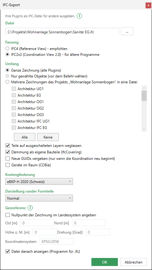
The export dialog box for all plug-ins. It opens with IFC export (ribbon › LuaCAD › Exchange, LuaCAD menu, right-click › LuaCAD) and with the commands IFCEXPORT and IFCOUT.
The IFC export dialog box: file with "…" (1), schema (2), scope with "several drawings of the project" and the list (3), the check boxes for layers, insulation, GUIDs, devices in the space (4), cost classification (5), display of round fittings (6), georeference (7), show file afterwards (8), OK (9)
Field
Effect
Default
Example
File, "…"
Where the file is written; "…" opens the save dialog box. If .ifc is missing, LuaCAD adds it.
next to the drawing, same name; unsaved drawing: Documents folder
the plumbing drawing of the ground floor next to its DWG
Only what was selected before the command; unavailable without a selection.
selected if objects were selected before
12 pipes of a riser
Scope › Several drawings of the project in one file
Only in a project with more than one drawing. The list below becomes available, the file name becomes the project name in the project folder.
not selected
–
List of drawings, All, None
Which drawings go into the file; missing ones are unavailable ("file missing").
the open drawing ("this drawing")
plumbing ground floor, plumbing first floor, heating ground floor
Leave out parts on layers that are off
Layers that are off or frozen stay out.
on
–
Insulation as separate elements (IfcCovering)
Insulation as an element of its own; off = without insulation.
on
–
Assign new GUIDs (only when coordination starts over)
All (or the selected) elements get new IFC GUIDs; LuaCAD asks first. Applies to this export only.
off
after a completely new design
Devices in the space (COBie)
Terminals and fixtures belong to the space instead of the level.
off
on for the handover to facility management
Cost classification
eBKP-H 2020 (Switzerland), DIN 276 (Germany), eBKP-H and DIN 276, none. The code comes from the property field on the part, from the part type or from the system.
eBKP-H 2020 (Switzerland)
none
Display of round fittings
Fine (small facets, large file), Normal, Coarse (small file).
Normal
Coarse
Georeference › State the origin of the drawing in the national grid
Makes the fields below available.
off
on
East [m], North [m], elevation above sea level [m], rotation [degrees], coordinate system
Position of the drawing origin on the map and rotation to north; the fields calculate and keep east, north and elevation to the millimeter (3 decimals), the rotation to 4 decimals – "2600000+120.457" becomes 2600120.457 when you leave the field.
0, 0, 0, 0, EPSG:2056
2,600,120.457, 1,200,340.25, 432.5, 0
Location of the IFC import
Only if the drawing comes from an IFC import with offset or rotation: original coordinates (exactly on top of the original IFC) or small coordinates, offset and rotation only in the map conversion.
Original coordinates
–
Show file afterwards
Opens the file afterwards in the program for .ifc.
on
–
OK, Cancel
OK writes; if the file already exists, LuaCAD asks whether to overwrite it. Cancel writes nothing.
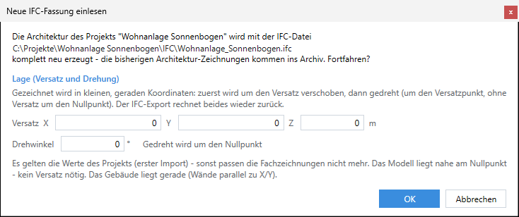
Opens after you choose the file, when you choose IFC import in a project or Update IFC … on the project palette.
The Read in new IFC version dialog box: the question with project and file (1), offset X/Y/Z (2), rotation angle (3), the note "The values of the project apply …" – here the model is already close to the origin and straight, so there is no suggestion (4), OK (5)
Field
Effect
Default
Example
Question
The architecture of the project is created completely anew from the IFC file – the previous architectural drawings go to the archive folder.
–
–
Offset X, Y, Z (m)
How far the model is moved; the fields calculate.
the values of the project
2,600,000 / 1,200,000 / 0
Rotation angle (°)
How much the model is rotated – around the offset point, without offset around the origin.
the value of the project
0
Note
Where the values come from; if the new version differs by more than 1 m, an orange line below shows the detected value and the project value.
–
–
Suggestion, Apply
Only if the new version is detected at an angle: it asks whether to align the building straight; Apply enters the angle.
–
–
OK, Cancel
OK reads in and replaces the architecture; Cancel leaves the project as it was.
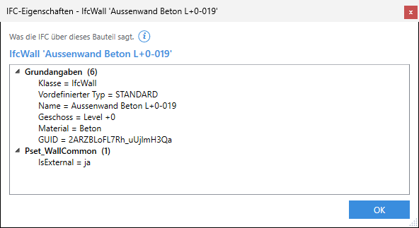
All data of an element or space of the architecture. Right-click › LuaCAD › IFC properties (architecture) …, then click an element (also inside an xref). The window title names class and name; you can drag the window larger.
The IFC properties window of a wall: title with class and name (1), basic data (2), the property set Pset_WallCommon of the IFC (3), OK (4)
Field
Effect
Default
Example
Header
Class and name of the element, or number and name of the space.
–
IfcWall 'Interior wall 12.5'
Note
Only if the project's IFC file is missing: then only the basic data are shown.
–
–
Basic data
Element: class, predefined type, name, type, level, space, material, GUID, plus from the IFC classification, groups/zones, layer (IFC), "contained in", tag. Space: space number, space name, occupancy, area, level, GUID, boundaries, neighboring spaces through doors.
expanded
space 0.12, neighboring spaces through doors 0.10, 0.13
Property sets
One group "set (count)" per set of the IFC with "property = value"; data from the element's type are marked "(Type)".
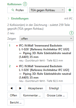
The Clashes section – the same in Piping 3D, Ventilation 3D, Drainage 3D (Tools page) and in the Block Library (Current Drawing page). Check, set up, work on the list of the drawing.
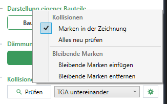
The Clashes section in Piping 3D (Tools page) after checking in the basement of the sample project: Check (1), check set "MEP against structure" (2), gear menu (3), settings, collapsed here – on the right "with IFC" (4), state and count "2 new" (5), Show (6), the list: two pipes through an interior wall of the IFC without an opening, "opening missing" (7), the buttons below (8)
Field
Effect
Default
Example
Check
Checks the drawing with the chosen check set (command of the plug-in); the result goes into the list. One undo step.
Markers in the drawing (check mark) · Check everything again · Insert persistent markers · Remove persistent markers.
markers on
Check everything again after a new IFC xref
Settings (expandable)
Scope, xrefs, minimum clearance, penetration depth, grouping, IFC groups, report openings, check insulation, check changes only – see Clash detection. Collapsed, the scope is shown at the right.
collapsed
–
Status line
"5 clash(es) in the drawing - last 812 parts checked (MEP against structure)", if applicable "last 3 of 812 parts", "2 xref(s) loaded …", "2 clash(es) on the selected parts".
"Not checked yet."
–
Count, Show
Number per status (new · open · accepted · resolved) and the filter of the list.
open
resolved, to see what the last check resolved
List
Per clash: number, status dot (red open, green accepted, gray resolved), the parts; below status, type, depth, comments, notes. Click = view on the location, parts selected or highlighted in xrefs.
–
click row 1 – zoom to the pipe/duct crossing
◀ ▶
Previous / next clash (in a loop).
–
–
Accept, Resolved, Open
Set the status of the selected clash (one undo step).
The gear of the Clashes section: Markers in the drawing (1), Check everything again (2), Insert persistent markers (3), Remove persistent markers (4)
Field
Effect
Default
Example
Markers in the drawing
Temporary spheres with number (red open, ring = new, green accepted, gray resolved, selected one yellow); at most 300; not in the drawing, not plotted.
on
off while drawing in a crowded plant room
Check everything again
Starts the check once without "Check changes only".
–
after replacing the IFC xref
Insert persistent markers
Circle + number per clash of the list on layer LuaCAD_ALG_Kollisionen (not plotted), color of the status; existing ones are replaced. One undo step.
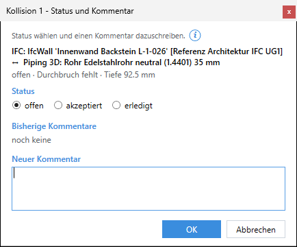
Button Comment … in the section or in the large list (also for several selected clashes). Title "Clash 3 - status and comment" or "4 clashes - status and comment".
The Status and comment dialog box: the clash with parts and type (1), status open / accepted / resolved (2), previous comments with name and time – none yet here (3), new comment (4), OK (5)
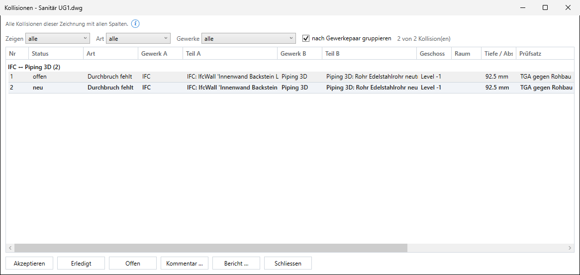
Button Large list … in the section. A window of its own "Clashes - <drawing>", modeless, resizable.
The large list of clashes: the filters Show, Type and Disciplines (1), group by discipline pair (2), the count (3), the group "IFC ↔ Piping 3D (2)" with all columns (4), the buttons Accept to Close (5)
Field
Effect
Default
Example
Show
Status filter: open · open + accepted · accepted · resolved · all.
all
open
Type
One type only (hard, insulation, too close, opening missing, opening too small, each possibly "(uncertain)").
all
opening missing
Disciplines
One discipline pair only.
all
"Ventilation 3D ↔ Piping 3D"
Group by discipline pair
Groups per discipline pair with a count.
unchecked
checked: "IFC ↔ Piping 3D (12)"
Count
"8 of 20 clash(es)".
–
–
Columns
No., status, type, discipline A, part A, discipline B, part B, level, room, depth / distance, check set, last found, comment, note; a click on the header sorts, columns can be moved.
sorted by no.
by depth
Rows
Click one = show the location; several with Ctrl/Shift; shortcut menu as in the section.
–
–
Accept, Resolved, Open, Comment …
For all selected rows.
–
5 openings resolved at once
Report …
Excel with exactly the visible rows in their order.
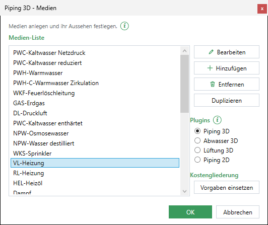
Create, change, duplicate and remove systems – for all plug-ins. It opens with gear menu › Settings › Systems in Piping 3D, Piping 2D, Drainage 3D and Ventilation 3D.
The system definitions opened from Piping 3D: the system list with "VL-Heizung" selected (1), Edit, Add, Remove, Duplicate (2), the plug-ins choice with Piping 3D (3), cost breakdown › Insert defaults (4), OK and Cancel (5)
Field
Effect
Default
Example
System list
The systems of the selected plug-in as "abbreviation-description"; double-click = Edit.
the first system selected
VL-Heizung
Edit
Opens the system dialog box with a copy; only OK takes it into the list.
–
change the description
Add
An empty system: abbreviation Neu, description Neues Medium, remark Keine Bemerkung, all display entries from CAD (no layer). Created in the Piping 2D list only for Piping 2D, otherwise for all 3D plug-ins.
substance liquid, catalog system group "not assigned" (with plug-ins = Ventilation 3D: gas and ventilation), discipline ALG
a system for laboratory compressed air
Remove
After a question it leaves the list; parts in drawings keep the ID and then show no system. In the Piping 2D list: if the system is also in a 3D plug-in, it only leaves Piping 2D.
–
a system never used
Duplicate
Copy with "abbreviation[n]" (first free number), new ID and layers of its own; in the Piping 2D list only for Piping 2D.
Which systems the list shows – a filter, not a property. The Attributes tab still shows the display entries of the calling plug-in.
the plug-in the dialog box was opened from
choose Drainage 3D to rename a drainage system
Take over from Piping 3D
Only with plug-ins = Piping 2D: fetches the systems of Piping 3D that are missing in Piping 2D, with the display of their routing line; saved with OK.
–
after a new system in Piping 3D
Cost breakdown › Insert defaults
Enters the default code for all systems without a code of their own; own codes stay. Missing if no breakdown is active.
–
"12 defaults entered …"
OK
Saves all systems and pushes values explicitly changed ByLayer to the layers of the open drawing; the pipe connectors of the drawing take the color of their system.
–
the command line names the layer LuaCAD_HZG_VL-Heizung
Cancel
Discards all changes of the dialog box.
–
–
Messages: a system with this name already exists – abbreviation and description together must be unique (the system dialog box stays open); the system was created but belongs to another plug-in than the one shown.
Edit one system – two tabs, General and Attributes. It opens with Edit (or double-click) and Add in the system definitions.
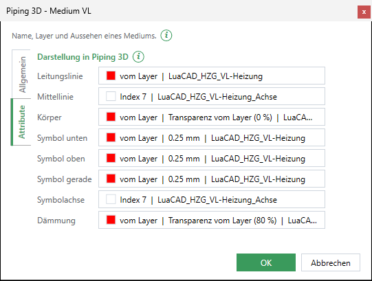
The dialog box of a system, Attributes tab: the tabs General and Attributes (1), the row Pipe line with "ByLayer | LuaCAD_HZG_VL-Heizung" and a red swatch (2), the row Insulation with "Transparency ByLayer (80 %)" (3)
Field
Effect
Default
Example
Abbreviation
Code by standard; may occur several times and may be empty.
Neu (Add)
VL
Description
With the abbreviation the name of the system and its layer. Abbreviation and description must not both be empty.
Neues Medium
Heizung
Remark
Free text.
Keine Bemerkung
Vorlauf
Catalog system group
The system group of the manufacturer catalogs (not assigned, heating, domestic water, process water, waste water, pressure drainage, sprinkler, fire water, cooling water, oil supply, ventilation, compressed air, gas supply, flue gas, steam, other).
not assigned (created with plug-ins = Ventilation 3D: ventilation)
heating
Substance
Liquid or gas.
liquid (created with plug-ins = Ventilation 3D: gas)
gas
Discipline
SAN, HZG, LUE, KAE, ELT, BRS, ALG or "without layer – current layer"; sets the layer name LuaCAD_<discipline>_….
ALG
HZG
Plug-ins
Check boxes Piping 3D, Drainage 3D, Ventilation 3D, Piping 2D; at least one.
the three 3D plug-ins (in the Piping 2D list: Piping 2D only)
Ventilation 3D only
Cost breakdown › eBKP-H
Code to type or choose (D08 filters); empty = default, "-" = none. A code the breakdown does not know is rejected.
empty
D05.04
Attributes › one button per display entry
Shows color, linetype, lineweight, transparency and layer; a click opens the attribute dialog box. Which entries appear depends on the calling plug-in (display entries).
All values of an entry to the clipboard, or from it into the entry; what the entry does not know is dropped. The line below says what was copied or pasted.
–
body of VL-Heizung into the body of RL-Heizung
OK
Checks name and plug-ins and takes the system into the list; it is saved only with OK in the system definitions.
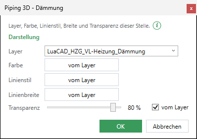
The display of one entry. It opens with the button of an entry on the Attributes tab of the system dialog box (title "<plug-in> - <entry>"); the same dialog box serves the attribute buttons of other settings. Only the rows the entry knows appear (body of Piping 3D: layer, color, transparency).
The attribute dialog box of the insulation entry: layer (1), color (2), linetype (3), lineweight (4), transparency with the ByLayer check box (5) – the transparency row exists only for body and insulation
Field
Effect
Default
Example
Layer
A layer of the drawing or a new name (created when inserting); empty = from CAD (current layer). The standard name of the system keeps the default layer, another name becomes a layer of the entry's own.
the layer of the system
LuaCAD_HZG_VL-Heizung
Color
GstarCAD color dialog box: ByLayer, ByBlock, color index, true color, color book.
per entry (centerlines fixed color 7, otherwise ByLayer)
Checked: the part shows the transparency of its layer; the value is the one for a new layer and, changed in the system definitions, goes to the layer of the open drawing. Unchecked: fixed value at the part.
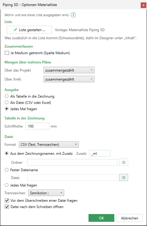
Where a list goes and under which name. Opens with "…" next to the button of the list (Piping 3D, Ventilation 3D, Drainage 3D also gear menu › Options); title "<plug-in> - Options <button>", for example "Piping 3D - Options bill of materials".
The "Piping 3D - Options bill of materials" dialog box: Design list with the name of the template (1), Combine with the check box Separate per system (2), quantities across several plans (3), output (4), table in the drawing with text height (5), file with format, file name, suffix, folder, delimiter (6), the two check boxes for the file (7)
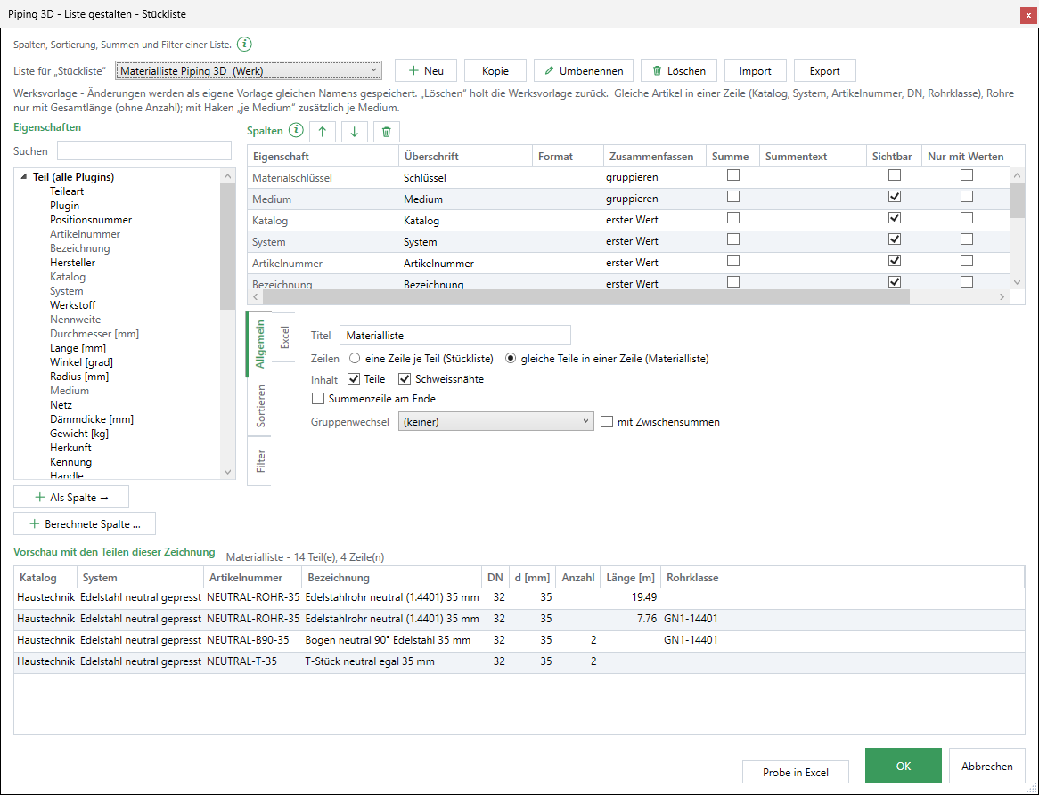
What a list contains – columns, sort order, totals, filter, Excel template – with a preview from the parts of the open drawing. Opens with Design list … in the list options; title "<plug-in> - Design list - <button>". The same dialog box in every plug-in with lists.
The "Piping 3D - Design list" dialog box with the factory bill of materials template of Piping 3D: at the top the choice of the list with New, Copy, Rename, Delete, Import, Export (1), on the left the properties with search and "Add column →" (2), on the right the columns (3), below the tabs General, Sort, Filter, Excel (4), at the bottom the preview (5), Preview in Excel, OK and Cancel (6)
Field
Effect
Default
Example
List for "<button>"
Which list template the button uses: the default templates and your own ones of this plug-in; "(default)" = supplied. Below it a sentence whether it is a default template or your own, and its description.
the selected one, otherwise the default template
the order list for the duct fabricator for the bill of materials of Ventilation 3D
New
New list (the name is asked): title {Liste}, rows according to the button, column Description (bill of materials: plus Count).
name "new list"
a list with article number and count only
Copy
Copy of the selected list under a new name.
name "<name> (copy)"
copy of the bill of materials of the pipes
Rename
Your own only; a name that already exists is rejected. A default template keeps its name.
–
"Material per catalog"
Delete
Delete your own list (with a question); if it is the changed version of a default template, the default template comes back. Default templates cannot be deleted.
–
delete your own version of the bill of materials of the pipes
Import, Export
Read list templates from a .luacadliste file (Import still reads the earlier extension .hvliste without renaming it) or write the selected one into a .luacadliste file. An imported one with the name of a default template replaces it; otherwise a duplicate name gets "(2)".
–
pass the office list on to colleagues
Properties › Search
Filters the tree by name or key.
empty
"wei" finds weight
Properties (tree)
All properties of the parts in groups: parts of all plug-ins, those of the plug-in, property fields, GstarCAD, further fields of the drawing, architecture (IFC), Count (sequence number, count). Gray = already a column. Tooltip = key.
the group of all plug-ins expanded
property field "construction phase"
Add column → (or double-click)
Adds the selected property as a column.
heading = name of the property; in a bill of materials Combine "sum" for numbers with a unit, otherwise "group"
"Weight" becomes a column with a sum
Calculated column …
Opens Calculated column; a double-click on a calculated column changes it.
–
Laenge/1000
Columns › arrows, trash can
Move the selected column forward/back or remove it. The "i" at the title explains Combine.
–
remove the pipe spec
Columns › Property
Display only; a calculated column shows "= expression".
–
= Laenge/1000
Columns › Heading
Header of the column.
name of the property
"Length [m]"
Columns › Format
Numbers: unit, digit = fixed decimals, ~2 = at most two, ohne0 = zero stays empty; separated by a colon.
empty = at most two decimals, unit of the property
m:2 → 24.35 instead of 24350
Columns › Combine
Only with "equal parts in one row": group, sum, count, first value, minimum, maximum, all values, all values with sequences as ranges (1-4).
group (or see "Add column")
No. with ranges → "1-40, 52"
Columns › Sum
Sum of this column in total and subtotal rows.
off
Length [m]
Columns › Total text
Fixed text in the total row; {Anzahl} = number of parts, {Zeilen} = number of rows.
empty
Total {Anzahl} parts
Columns › Visible
Off = for grouping only, not output.
on
a key that only separates
Columns › Only with values
The column only if at least one part has a value.
off
"Delivery" only with coiled pipe
Columns › Only when checked
The column applies only with a switch of the list options; the list shows the switches of the template.
(always)
system only with "Separate per system"
General › Title
Title of the list; {Liste}, {Zeichnung}, {Datum}.
{Liste} with New
{Liste} - {Datum}
General › Rows
one row per part (parts list) · equal parts in one row (bill of materials).
according to the button
–
General › Content
Only if the plug-in has several row sources: one check box per source (parts, welds, cuts, protective caps, connectors, nodes). All on = all.
all on, unless the default template names parts only
Drainage: add welds
General › Total row at the end
Sum of the columns with "Sum" or total text.
off (some default templates on)
on
General › Group by, with subtotals
With every new value a row "<property>: <value>", with the check box the subtotal per group (with a total row only from two groups on).
(none), off
catalog with subtotals
Sort › Sort by, type, descending, empty last, only when checked
One sort key per row; type text · natural (3-2 before 3-10) · number · character · number or text; "+", arrows, trash can.
new row: type text, (always)
DN as a number, descending
Filter › Property, condition, value
Only parts to which all rows apply; condition is · is not · contains · less than · greater than · is empty · is not empty; with is/is not several values separated by semicolons.
no filter; new row "is"
system is KW;WW
Excel › Template
Your own .xlsx/.xltx (only these); empty = standard sheet. The list button chooses it.
empty
Order_company.xlsx
Excel › Sheet
Name of the sheet.
empty = the first one
"Material"
Excel › Start cell
First data row = template row (format, formulas).
empty = below the last used row
B8
Excel › Write header row
Write the column headings.
on
off if the template has them
Preview with the parts of this drawing
Up to 300 rows; above it the title with the number of parts and rows, and an error of the template.
–
120 parts give 18 rows
Preview in Excel
Open the preview as an Excel file (with the Excel template).
–
check the company header
OK
Checks (name, a visible column, every column with a property, one column to group by, start cell, Excel template), saves all your own lists and sets the selected one for the button.
A column that calculates. Opens with Calculated column … in the list layout dialog box (or a double-click on a calculated column); title "<plug-in> - Calculated column". No picture of its own (small window).
Field
Effect
Default
Example
Expression
+ − * / and parentheses over properties and numbers (period as decimal separator); names with other characters in [square brackets]. Below it the result for the first part of the drawing or the error. If a value is missing, the cell stays empty.
empty
Laenge/1000
Format
As Format in Design list.
0.00
0.00 → 1.25
Heading
Header of the column.
empty = the expression
"Length m"
Examples (click inserts)
Ready-made expressions, for example length in meters, height of the part, weight times count.
–
Gewicht*Anzahl
Properties (double-click inserts), Search
The numeric properties; "Count" = the parts of the row in the list, otherwise 1.
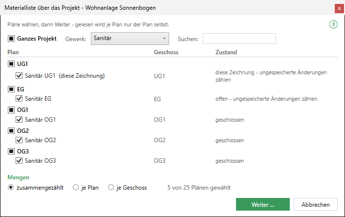
Which plans a list across several plans reads. Opens with Bill of materials across the project … or across xrefs … (Block Library: Extract across …); the title names the button and the project. The arrow keys move from check box to check box, the spacebar toggles.
The dialog box "Bill of materials across the project" of the sample project: header check box Entire project (1), discipline and search (2), the plans per level with their state (3), quantities (4), "5 of 25 plans selected" (5), Next … and Cancel (6)
Field
Effect
Default
Example
Short line with "i"
What is read; the "i" explains that no plan is opened, saved or changed.
–
–
Entire project / All xrefs
Header check box for all selectable rows – including those the filter hides; half = some. Fully on is remembered as "all": Update lists also takes new plans.
according to the check boxes of the rows
fully on – all levels of the heating
Discipline
Across the project only: shows only the plans of one discipline (all disciplines); the check boxes stay.
your own discipline
Plumbing
Search
Shows only plans whose name, file or level contains the text.
empty
"floor 1"
Level (check box)
Across the project: all plans of a level on/off; "without level" last.
–
ground floor
Plan (check box)
One plan; the tooltip shows the file. Across xrefs indented by nesting, "(this drawing)" at the top. Gray = not selectable (file missing, not found).
project: your own discipline and this drawing; xrefs: this drawing, loaded and hidden xrefs; the same file in a second place not
only the ground floor and the 1st floor
Level, Count
Level of the plan; Count across xrefs only: how often each part counts (×).
–
×2
Status
this drawing · open (unsaved changes count) · closed · being edited by … (saved state) · file missing · loaded · hidden – counts · unloaded – read from the file · not found; plus "clipped (all parts count)" and "also via …".
–
open – unsaved changes count
Quantities
combined · per plan · per level (as in the list options).
combined
per plan
n of m plans selected
Display only.
–
3 of 8 plans selected
Next … (Enter)
Reads and outputs; without a check box a message asks for at least one plan.
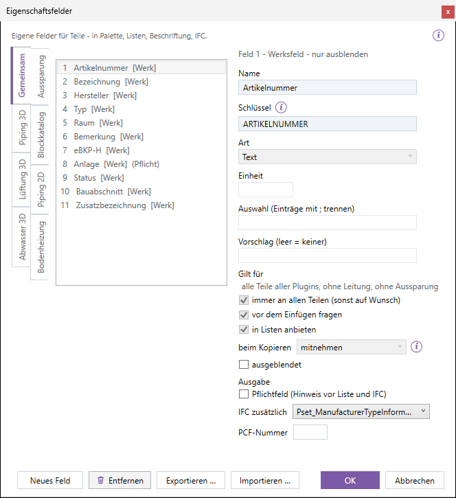
Which fields exist – the same dialog box in all plug-ins. It opens with gear menu › Properties › Property fields … on the tab of the plug-in, from the Annotation palette on Common.
The Property fields dialog box (here from the Annotation palette, Shared tab): Shared tab and one tab per plug-in (1), the list of fields with number, default fields marked "Werk", a required field marked (Pflicht) (2), name, key and type (3), choices and suggestion (4), applies to (5), always on all parts, ask before inserting, offer in lists (6), when copying (7), required field, IFC additionally, PCF number (8), New field, Remove, Export, Import (9)
Field
Effect
Default
Example
Short line with "i"
What property fields are, "always" and "on request".
–
–
Tabs
Common (fields without a plug-in) and one per plug-in: Piping 3D, Ventilation 3D, Drainage 3D, Openings, Block Library, Piping 2D, Floor Heating.
the tab of the calling plug-in
Piping 3D
List of fields
"No. Name [unit]", default fields gray with a lock mark, plus "(hidden)", "(required)".
default fields of the tab
"50 Fire compartment (required)"
Heading on the right
"Field 50 (new) – custom field" or "Field 35 – default field – hide only".
–
–
Name
What appears in the palette, lists and annotation; fixed on default fields.
"New field"
Fire compartment
Key (with "i")
Fixed name for placeholders, import and export (A–Z, 0–9, _); made from the name, changeable only on a new field.
from the name
FIRE_COMPARTMENT
Type
Text, number, whole number, length (mm), yes / no, choice from a list.
text
choice from a list
Unit
Numbers only; appears after the name ("Test pressure [bar]"). Length without a unit = mm.
empty
kg
Choice (separate entries with ;)
The entries of the list; CODE=Name stores the code and shows the name. A choice needs at least one entry.
empty
FC-01;FC-02;FC-03
Suggestion (empty = none)
The fixed suggestion of an empty field.
empty
FC-01
Applies to
On a plug-in tab one check box per part group; on Common "all parts of all plug-ins". Display only on default fields.
all part groups on a plug-in tab
valve and manufacturer product only
always on all parts (otherwise on request)
On: the field is on every part of its part groups, even empty. Off: only once it is attached in the palette with "Add field …".
off (default fields always on)
on
ask before inserting
The field appears in the dialog box before inserting and in the palette area "Property fields of the next …" – only together with "always on all parts".
off
on for plant
offer in lists
The field can be chosen as a column when laying out a list.
on
–
when copying (with "i")
keep, clear or renumber.
keep
renumber for a number of your own
hidden
The field is switched off (also a default field).
off
–
Output › Required field (note before list and IFC)
See Required fields. A field "on request" only counts on parts that carry it.
off
on
Output › IFC additionally
Only the LuaCAD property set, IfcElement.Tag or a property of Pset_ManufacturerTypeInformation (Manufacturer, ArticleNumber, ModelLabel, ModelReference) or Pset_ManufacturerOccurrence (SerialNumber, BarCode, BatchReference).
1–99 or empty; only the PCF export of process piping.
empty
5
New field
A custom field with the next free number from 50 on the chosen tab. If 50–99 are taken, LuaCAD says so.
–
–
Remove
Only a new field that is not saved yet; hide a saved one.
–
–
Export … / Import …
The fields as an XML file; on import the key decides, beforehand the list of changes to confirm.
–
the office fields on a second computer
OK / Cancel
OK checks (numbers, key, name, choice, duplicate PCF number) – an error appears in red at the bottom, the dialog box stays open; then the catalog applies in all plug-ins. Cancel discards.
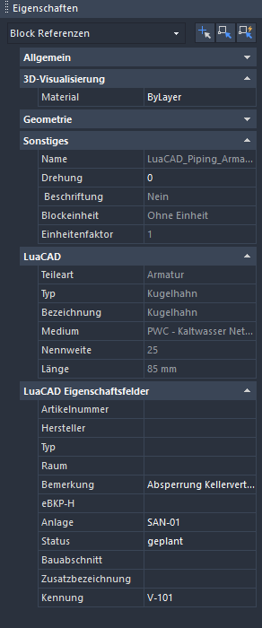
Click one part (or several) without a command – the LuaCAD property fields category in the Properties palette of GstarCAD.
The Properties palette with a selected ball valve: the LuaCAD category with the values of the plug-in (type, system, nominal diameter …), read-only (1), in the LuaCAD property fields category (5) the values set when inserting: remark (2), plant SAN-01 (3) and tag V-101 (4)
Field
Effect
Default
Example
one row per field
An entry applies to the selected parts, one undo step; numbers calculate, choice and yes / no as a list; an invalid entry is refused.
empty = suggestion
plant SAN-01
Suggestion
Empty shows the suggestion (description of the part, room, value of the pipe, fixed suggestion). Entering the same saves nothing, clearing brings it back.
–
status "planned"
Tag
Without a tag "(next free: V-004)"; "+" assigns it, one of its own per selected part.
–
+ on three parts → V-004, V-005, V-006
Add field …
"add: …" attaches a field on request, "remove: …" removes it.
–
add: test number
LuaCAD category
Values of the plug-in and – on catalog parts – article number, description, manufacturer from the catalog, read-only.
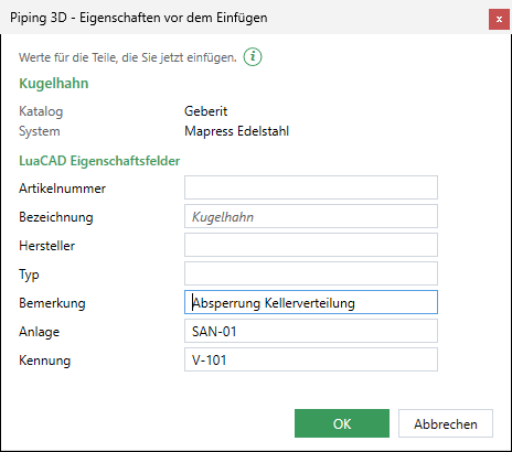
"<plug-in> - Properties before inserting" appears before the cursor if Show properties before inserting is checked above the parts list and the part has fields with "ask before inserting" (otherwise the part hangs at the cursor right away). Esc at the cursor returns here.
The Properties before inserting dialog box of Piping 3D for a ball valve: the title of the part (1), catalog and product line from the pipe, read-only (2), the LuaCAD property fields category with remark, plant SAN-01 and tag V-101 – V-001 was suggested (3), OK and Cancel (4), the "i" at the top (5)
Field
Effect
Default
Example
"i" at the top
Explanation and "More in the online help".
–
–
Title of the part
What is inserted.
–
ball valve DN 25
Catalog, product line
Read-only; "from the pipe" if the part gets them from the pipe.
–
from the pipe
one row per field
The fields with "ask before inserting" that apply to the part group; empty = the part does not get this value. A value equal to the suggestion is not saved.
the values of the last round, otherwise those last entered for this type, otherwise the suggestion
plant SAN-01
Tag
The next free one by the pattern; counts up per inserted part.
V-001
V-101 → V-102 …
OK
Checks the entries (error in red, the field gets the focus); then the part hangs at the cursor.
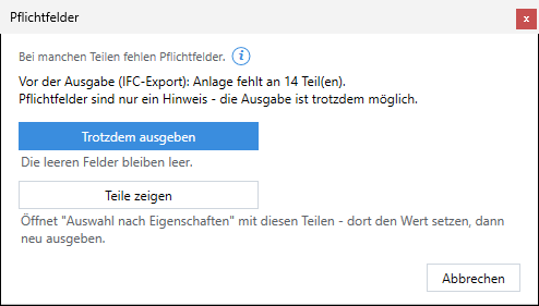
Appears before every list and before the IFC export if a required field is empty on parts of this drawing. By default no field is required.
The Required fields prompt before the IFC export: "Before the output (IFC export): Plant is missing on 14 part(s)" (1), Output anyway (2), Show parts (3), Cancel (4)
Field
Effect
Default
Example
Question
"Before the output (…): <field> is missing on n part(s)" per empty required field, plus "Required fields are only a note". The same on the command line.
–
"Before the output (list "Parts list"): plant is missing on 23 part(s)"
Output anyway
The output runs, the empty fields stay empty.
highlighted
–
Show parts
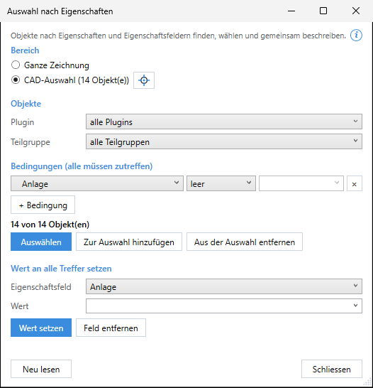
Nothing is output; Select by properties opens with these parts as the scope, the condition "<first field> empty" and the same field to set.
Ribbon › LuaCAD › Tools › Select by properties (command LUACADEIGENSCHAFTENWAEHLEN, also in the LuaCAD menu). The window is modeless; whatever changes the drawing or sets the selection runs as a command of its own.
The Select by properties window, opened with "Show parts" from the Required fields prompt: scope with Entire drawing and Current selection with the crosshair (1), plug-in and part group (2), the condition "Plant – empty" (3), + Condition (4), the matches "14 of 14 object(s)" with Select, Add to selection, Remove from selection (5), set a value on all matches with property field, value, Set value, Remove field (6), Reload and Close (7)
Field
Effect
Default
Example
Scope › Entire drawing
Searches model space: all parts of the plug-ins, plus foreign objects with property fields.
on, if nothing is selected when opening
–
Scope › Current selection (n object(s))
Searches only these objects (with their partners), also foreign ones without fields.
on if something was selected when opening
select one part of a level with a selection window
Crosshair
Select the objects again (Enter = done; Esc = the scope stays).
–
–
Plug-in
"all plug-ins", the plug-ins in the scope, "other objects".
all plug-ins
Piping 3D
Part group
The part groups in the scope.
all part groups
valve
Condition › Property
Categories LuaCAD, LuaCAD property fields, GstarCAD; typing jumps to the name.
(choose property) = no condition
article number
Condition › Comparison
is, is not, contains, begins with, empty, not empty, greater than, less than, between (then a second field).
is
empty
Condition › Value
Type it or choose from the values in the scope; gray for empty / not empty.
empty
25
× / + Condition
Remove or add a row; all rows must be met (AND).
one row
DN is 25 AND tag empty
Matches
"n of m object(s)" – m = objects of plug-in and part group in the scope; recalculated after every change.
–
7 of 52 object(s)
Select
Selects the matches in GstarCAD; in plan view zoomed to them (at least 500 mm margin).
–
–
Add to selection / Remove from selection
Work with the existing selection.
–
first select ball valves, then add check valves
Property field
The field that is set; "(on request)" follows fields on request.
the first field (article number)
fire compartment
Value
A list for choice and yes / no, otherwise the values in the scope to choose from.
empty
FC-03
Set value
To all matches, one undo step; a default field only where it applies (the others reported as skipped); empty for a field "always" = remove field.
Gear menu › Properties › Property fields of a pipe … (Piping 3D, Piping 2D, Ventilation 3D, Drainage 3D), then click a part or a line. Title "<plug-in> - Property fields of the pipe", in Ventilation 3D "… of the duct network". Image: see Ventilation 3D.
Field
Effect
Default
Example
Note (gray)
The values apply to every part without an entry of its own; description, additional description, room and remark only describe the pipe itself.
–
–
one row per field of the pipe
The fields that apply to the part group pipe of the plug-in, plus every field with an entry; empty = entry removed.
the values of the pipe
plant HTG-02
OK / Cancel
OK writes to all lines or the duct network, one undo step; the command line reports how many objects were changed.
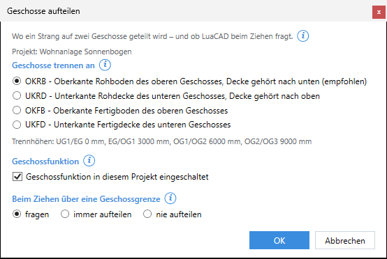
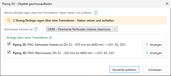
The settings of the level function for the project of the active drawing. It opens with gear menu › Levels › Divide across levels settings … (Piping 3D, Drainage 3D, Ventilation 3D) or project palette › shortcut menu. The first time you divide in a project the same dialog box appears as "Divide levels at" with the upper part only (dividing plane).
The Divide across levels settings dialog box: project (1), "Divide levels at" with TOS, BOS, FF, FC (2), the dividing elevations (3), check box Level function (4), "When drawing across a level boundary": ask, always divide, never divide (5), OK (6)
Field
Effect
Default
Example
Project
Display only: the name of the project.
–
"Project: 2000 Sonnenbogen Residences"
Divide levels at
TOS of the upper level (the slab belongs to the level below, recommended) · BOS of the lower level (the slab belongs to the level above) · FF of the upper · FC of the lower. Applies to everything divided from now on; existing break points stay. A different reference level chosen earlier appears as TOS.
the reference level of the project, otherwise TOS
BOS
Dividing elevations
Display only: for each level boundary the elevation of the chosen reference level; if it is missing on a level, TOS of the upper level applies there. Changes with the choice above.
–
"EG/OG1 3.00 m" (TOS), "EG/OG1 2.75 m" (BOS) in the sample project
Level function switched on in this project
Off = no prompt when drawing, no dividing, existing level joints are ignored. Stored in the project file. Settings dialog box only.
on
off for a project in which only one level is worked on
When drawing across a level boundary
ask · always divide · never divide – applies to you in all projects. Settings dialog box only.
ask
never divide – you prefer to divide at the end with "Divide objects across levels"
OK, Cancel
OK writes; Cancel changes nothing. With "Divide levels at", Cancel means nothing is divided.
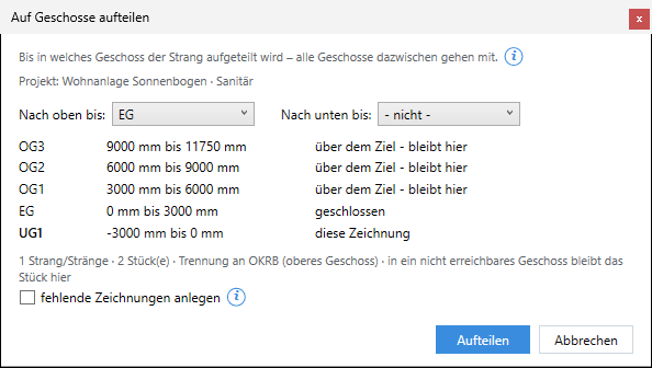
Up to which level the selected risers are distributed. It opens after selecting with Divide across levels … (palette of the plug-in, gear menu › Levels, project palette).
The Divide across levels dialog box: "Project · discipline" (1), "Up to" and "Down to" (2), the table of the levels with elevation range and state (3), the summary (4), check box "create missing drawings" (5), Divide and Cancel (6)
Field
Effect
Default
Example
Project · discipline
Display only: the project and the discipline of this drawing – the pieces go into this discipline.
–
"Project: 2000 Sonnenbogen Residences · Plumbing"
Up to, Down to
The target level in each direction; all levels in between always go along. "- none -" = not in this direction.
the level in which the risers end (with several, the farthest)
riser UG1 to OG3, Up to OG2
Table
For each level (topmost first) the elevation range and the state: "this drawing", "open", "closed", "being edited by …", "read-only", "drawing missing", "no drawing of this discipline - stays here", "above the target - stays here", "below the target - stays here". For information only.
–
"OG1 3.00 to 6.00 m closed"
Summary
Risers, pieces, dividing plane and side; recalculated with every choice.
–
"1 riser(s) · 3 piece(s) · divided at TOS (upper level) · …"
create missing drawings
If a level in the target has no drawing of this discipline, LuaCAD first creates it from the template and then divides (separate commands). Without the check the piece stays here.
off
Ventilation OG3 does not exist yet – it is created
Divide
Cuts and writes the pieces: closed drawings are saved, open ones changed but not saved, drawings that cannot be reached – the piece stays here (command line). One undo step in your drawing.
–
"Divided: 1 riser(s), 2 piece(s) written into 2 drawing(s), 1 piece(s) stay in this drawing."
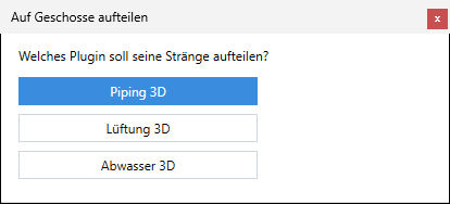
From the project palette (shortcut menu › Divide across levels …) if more than one plug-in with the level function is loaded: "Which plug-in should divide its risers?"
The question Which plug-in: one button per loaded plug-in, the first one highlighted (1)
Field
Effect
Default
Example
One button per plug-in
Starts "Divide across levels …" of this plug-in (selecting at the cursor).
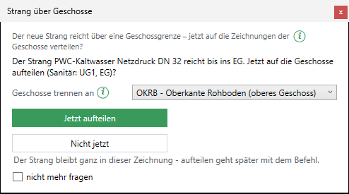
The prompt after a drawing command when the new riser crosses a dividing elevation by at least 10 mm and "When drawing across a level boundary" is set to ask.
The Riser across levels prompt after inserting a riser in UG1: "The riser … reaches into EG. Divide it across the levels now (Sanitary: UG1, EG)?" (1), "Divide levels at" (2), "Divide now" (3), "Not now" (4), check box "Don't ask again" (5)
Field
Effect
Default
Example
Question
Display only: the riser, how far it reaches, the discipline and the levels.
–
"The riser CW reaches into OG1 …"
Divide levels at
One of the four main reference levels; with "Divide now" it is remembered in the project and the risers are checked again with it.
the reference level of the project, otherwise TOS
TOS
Divide now
Starts dividing as a command of its own, up to the level you drew to. If several new risers have different targets, the question names all of them ("2 new risers reach across the level boundary - up to EG, OG1 …") and each riser is divided up to its own target (one step per target).
preselected
riser UG1 to OG1 – EG and OG1 get their piece; a second riser that only reaches into EG is only divided up to EG
Not now
The riser stays whole here; divide later with "Divide across levels …" or "Divide objects across levels …". Closing the window has the same effect.
–
draw the whole system first
don't ask again
Remembers the answer as "always divide" or "never divide"; reset in Divide across levels settings or the LuaCAD settings.
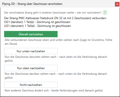
The prompt when a divided riser (with a level joint) is moved and something on other levels is attached to it. Title with the plug-in ("Piping 3D - Riser across levels moved").
The Riser across levels moved prompt: "The riser … is connected to 2 level(s)" and one row per level (1), "Follow everywhere" (2), "Follow only below" (3), "Follow only above" (4), "Do not follow" (5)
Field
Effect
Default
Example
Question
Display only: for each level (topmost first) below/above, the number of parts and whether the drawing is open or closed.
–
"OG1 (above): 1 part(s) - drawing is closed"
Follow everywhere
All connected levels above and below follow (position in plan, elevation at the joint), from joint to joint.
preselected
UG1 and OG1 follow by 200 mm
Follow only below
Only the levels below; the link upward is released afterwards. Grayed out if nothing is attached below.
–
only UG1 follows
Follow only above
Only the levels above; the link downward is released. Grayed out if nothing is attached above.
–
only OG1 follows
Do not follow
No other level changes; both links are released.
–
moved on EG only
Esc, closing the window
Cancel: your change is taken back, nothing is released.
–
moved by mistake
If a target drawing of the chosen side is open, Drawing is open follows.
The same question for a riser without a level joint (only drawn, never divided) in Piping 3D and Drainage 3D on which pipes of other levels end. Title with the plug-in.
Picture coming soonThe prompt Follow on the other levels: list of the levels with the number of pipes and open/closed (1), "Follow" (2), "Do not follow" (3)
Field
Effect
Default
Example
Question
Display only: "Pipes on other levels are attached to this riser:" and one row per level.
–
"OG1: 1 pipe(s) - drawing is closed"
Follow
The pipes on the other levels follow the riser. Open drawings are changed but not saved.
preselected
the pipe on OG1 ends at the riser again
Do not follow
This drawing only; on the other levels the pipes then end next to the riser. Closing the window has the same effect.
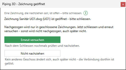
Appears after "Follow everywhere/only below/only above" if a target drawing of the chosen side is open, being edited by someone else or read-only. Following only happens in closed drawings.
The Drawing is open prompt: "Drawing … UG1.dwg (UG1) is open – please close it." (1), "Try again" (2), "Do not follow" (3)
Field
Effect
Default
Example
Obstacles
Display only: for each drawing "is open - please close it", "is being edited by … - please have it closed there" or "is read-only - please remove the write protection".
–
"Drawing Plumbing OG1.dwg (OG1) is open - please close it."
Try again
Checks again; if everything is closed, it follows, otherwise the question appears again.
preselected
OG1 closed, Try again
Do not follow
No other level changes, not later either; the link is released.
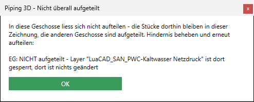
A report with OK if nothing could be written into a target drawing (missing, locked, layer locked, error). Title with the plug-in. After dividing it says "Not divided everywhere": the piece for that level stays in your drawing, the other levels are divided – remove the obstacle and divide again. Example: riser from UG1 to OG1, in the plumbing drawing of EG the layer of the cold water is locked – OG1 gets its piece, the piece for EG stays in UG1, the row reads "EG: NOT divided - layer … is locked there". After following it says "Not followed everywhere": the pipe there now ends next to the riser. One row per drawing with the reason; the command line says the same.
The window Piping 3D - Not divided everywhere: the sentence at the top (1), the row per drawing with reason – here EG with a locked layer (2), OK (3)
Field
Effect
Default
Example
Sentence at the top
Display only: what happens to the pieces (dividing: they stay here; following: the pipes end next to the riser).
–
"These levels could not be divided into - the pieces for them stay in this drawing …"
Rows
Display only: level and reason.
–
dividing: "OG1: NOT divided - layer … is locked there, nothing was changed there"; following: "OG1: NOT followed - layer … is locked there …"
Checks all risers of the drawing from Piping 3D, Drainage 3D and Ventilation 3D that reach across a dividing plane. It opens with Divide objects across levels … (palette of one of the three plug-ins, gear menu › Levels), after the help with a picture "Dividing objects across levels". It appears as an issues list with check boxes (not modal).
The Divide objects across levels list: "Divide levels at" (1), rows per riser with check box, elevation range and levels (2), "Show" (3), "Divide selected" (4)
Field
Effect
Default
Example
Sentence at the top
Display only: how many risers reach across a dividing plane.
–
"2 riser(s) reach across a dividing plane - set the check boxes and divide."
Divide levels at
One of the main reference levels; another choice recalculates the list, it is remembered in the project when dividing.
the reference level of the project, otherwise TOS
FF → one more riser reaches across it
Check box per row
"Riser ; elevation range → levels", grouped under "Risers across a dividing plane", with the plug-in. Without the check the riser stays. Rows for parts placed by hand (Drainage 3D) have no check box.
on
"PWC DN 32 ; -550 mm to 4100 mm → EG, OG1"
Show
Shows the riser in the drawing; the list stays open.
–
zooms to the vertical duct in the shaft
Divide selected
One divide command per plug-in and target (its own undo step), up to the level in which the riser ends.
–
1 Piping 3D riser, 1 Ventilation 3D riser → 2 steps
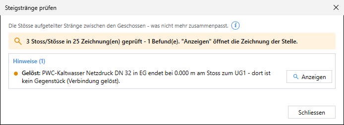
Checks every break point with a level joint against its counterpart on the neighboring level of the same discipline – nothing is changed. It opens with Check risers … (gear menu › Levels, project palette › shortcut menu); without an issue only a sentence on the command line. It appears as an issues list, errors and notes separate.
The Check risers issues list: the sentence "… joint(s) checked in … drawing(s)" (1), issues by type (2), "Show" (3)
Field
Effect
Default
Example
Sentence at the top
Display only: joints, drawings and issues.
–
"4 joint(s) checked in 3 drawing(s) - 1 issue(s)."
Issue Released, Offset, Dividing elevation, No drawing, Taken back
Notes: no counterpart (over 50 mm), counterpart up to 50 mm next to it, break point no longer at the dividing elevation, no neighboring level of this discipline, U in one drawing only (this session).
–
"CW in UG1 ends at 0 m at the joint to EG - there is no counterpart (link released)."
Issue Elevation gap, Jump
Errors: elevation missing or overlapping (over 1 mm); system or nominal size changes without a fitting.
–
"CW: 50 mm are missing or overlap in elevation between EG and OG1."
Show
Opens or activates the drawing of the place and shows it.
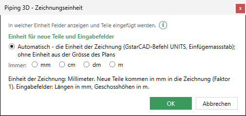
Chooses the units for new parts and input fields – the same dialog box in all plug-ins. It opens with Drawing units … in the LuaCAD settings (LuaCAD tab › Info) or in the gear menu of a plug-in (Piping 3D: gear menu › Settings).
The Drawing units dialog box from the LuaCAD settings: Automatic (1), Always: mm, cm, dm, m (2), the line "Units of the drawing …" with source, factor and the unit of the fields – here a drawing in millimeters (3), OK (4)
Field
Effect
Default
Example
Sentence at the top with "i"
Says in which units fields show values and parts are inserted – the "i" explains what always stays in mm, % and °.
–
–
Automatic – the units of the drawing …
Each drawing sets its own units (UNITS); without units from the size of the plan; if uncertain, the command line asks once at the first insertion.
selected
a plan in cm → new parts with factor 0.1, fields in cm
Always: mm, cm, dm, m
These units for every drawing, whatever the drawing says. Inches are not released yet and are therefore missing.
–
"m" for site plans → a pipe of 1500 mm is 1.5 units long
This drawing …
Display only, for the open drawing: where the units come from, unit and factor of new parts, whether the units are uncertain, and the units of lengths and floor-to-floor heights in the fields. Without a drawing: no drawing open.
–
new parts in m (factor 0.001), fields: lengths in m, floor-to-floor heights in m
OK, Cancel
OK stores the choice for all plug-ins, open fields convert; Cancel changes nothing.
–
OK – the Piping 3D palette now shows the elevation in m
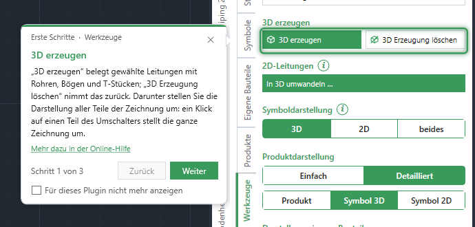
Explains a palette page field by field; it appears to the left of the palette. It comes when you open a page and Getting started is active; by hand with gear menu › Help › Show getting started or the "i" of the page › Show step by step.
The Getting started card to the left of the palette: header "Getting started · page" (1), title and text of the step (2), the highlight frame on the field in the palette (3), "More in the online help" (4), "Step 1 of 3" with Back and Next (5), check box "Don't show again for this plug-in" (6), close button (7)
Field
Effect
Default
Example
Header, title, text, highlight frame
Which page, which step, what the framed field does.
–
Getting started on the Pipe page, step "System"
More in the online help
Opens the page in detail in this help – only if there is a section for it.
–
opens the Pipe page section of Piping 3D
Step n of m, Back, Next / Finish
Leaf through; at the last step Next is called "Finish".
step 1
"Step 2 of 4"
Don't show again for this plug-in
With Finish or the close button: Getting started and all insertion help no longer appear by themselves in this plug-in (the same switch as "Getting started active").
off (checked if the plug-in is already off)
checked, Finish – Piping 3D without cards
Close button
Closes the card; without the check box it does not come back in this session, but at the next start.
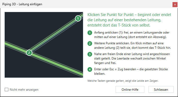
A window with a picture before the first click of a workflow at the cursor (title "plug-in – workflow", such as "Piping 3D - Insert pipe"). It appears every time the function starts, until "Don't show again" is checked; without a command through the "i" of the palette page › "Insertion help: …". It has no "i".
The insertion help "Insert pipe": title (1), picture with numbered clicks (2), lead sentence (3), steps 1 to 4 with the same numbers (4), "The bar at the cursor shows which keys apply right now." (5), check box "Don't show again" (6), "Online help" (7), Close (8)
Field
Effect
Default
Example
Picture
The workflow with numbered clicks in the color of the plug-in.
–
(1) start, (2) click in the middle of a pipe = tee
Lead sentence, steps 1–4
What happens, in the order of the clicks; keys by their name. Below, the sentence about the action bar (missing for workflows without one).
–
"Enter or Esc = end the run – the placed segments stay."
Don't show again
Only this one help no longer appears by itself; on again in the LuaCAD settings › Notices and prompts, or clear the check box here (through the "i" of the page).
off
"Insert pipe" off – "Draw parallel pipes" still appears
Online help
Opens the workflow in detail in this help; only there if a page exists for it.
–
opens "Inserting a pipe" in Piping 3D
Close (Enter, Esc, close button)
Closes only this time; the workflow starts anyway.
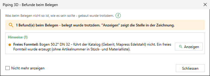
Shows after a workflow what was built although it should not be like that (title e.g. "Piping 3D - issues when assigning"). It only appears with at least one issue – after Generate 3D in Piping 3D, with Check risers, as a list for selecting with Divide objects across levels – and stays at the bottom right, not modal.
The issues list at the bottom right after Generate 3D: the sentence at the top "1 issue(s) when assigning – assigned anyway …" (1), the Notices group with a row "Free fitting: …" (2), "Show" (3), check box "Don't show again" (4), Close (5)
Field
Effect
Default
Example
Sentence at the top with "i"
What ran; the "i" explains errors, notices and Show.
–
"1 issue(s) when assigning – assigned anyway."
Errors (n), Notices (n)
One row per issue: red dot = error (usually an adjustment is needed), orange dot = notice (information); the kind in bold at the start.
–
notice "Free fitting: elbow 60° DN 20 …"
Show (or a click on the row)
View to the place, parts highlighted, a sphere as a marker; a place in another drawing opens or activates that drawing. The drawing never changes.
–
zooms to the corner with the free elbow
Message at the bottom
The objects of this row no longer exist; the drawing of this list is not the active one; the drawing of this place cannot be opened.
–
part deleted in the meantime
Don't show again
Only in the list after assigning: the plug-in no longer shows it, the command line still names the issues. On again: gear menu › Options › "Show list after assigning" or LuaCAD settings › Notices and prompts.
off
checked – after Generate 3D only the sentence in the command line
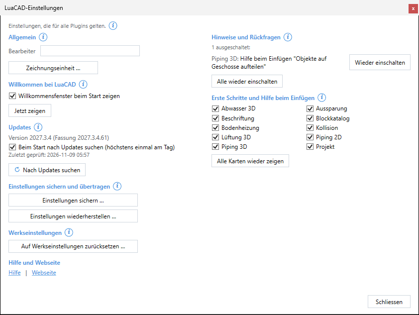
The right part of the LuaCAD settings (LuaCAD tab › Info › LuaCAD settings). The other areas are under LuaCAD settings.
The LuaCAD settings, on the right the Notices and prompts section: "2 switched off:" (1), per row the plug-in and what is switched off, e.g. "Piping 3D: insertion help …" (2), "Switch on again" (3), "Switch all on again" (4), below Getting started and insertion help with one check box per plug-in (5) and "Show all cards again" (6)
Field
Effect
Default
Example
n switched off: / No notices or prompts switched off.
How many places are off right now.
"No notices or prompts switched off."
"2 switched off:"
Row "plug-in: what"
One place that is switched off: welcome window, dividing across a level boundary while drawing, list of issues after assigning, editing with CAD commands, 2D objects after converting, isometric without weld, connecting to another system, other system or level at the start, heated areas at a new leader corridor, insertion help (with the title of the help).
–
"Piping 3D: Editing with CAD commands: remembered …", "Piping 3D: insertion help "Insert pipe""
Switch on again
This place back to its default; the row disappears. Applies immediately.
–
the prompt when moving a network with MOVE comes again
Switch all on again
All rows at once.
–
"3 notices and prompts switched on again. Applies immediately."
Getting started and insertion help › check box per plug-in
The same switch as gear menu › Help › Getting started active.
on
clear the check box for Ventilation 3D – no more cards and help there
Show all cards again
Releases all cards and insertion help of all plug-ins, switches plug-ins that were off back on.
–
"All cards and help appear again (12 markers removed)."