
Risers across levels (level function)
What the level function is for
In a project every level has its own drawing for each discipline: the plumbing drawing of UG1, of EG, of OG1 … A riser, a stack or a duct riser, however, runs through several levels. The level function distributes such a riser across the drawings of the levels: each piece goes into the drawing of its level, in the discipline of the drawing you are working in. Afterwards the pieces know about each other – if you move the riser on one level, LuaCAD asks whether the other levels follow.
It applies to Piping 3D (risers), Drainage 3D (stacks) and Ventilation 3D (vertical ducts and round ducts). It works the same way in all three plug-ins.
The typical way to work: you draw on the lowest level of the system and draw the riser up from there. If it reaches across a level boundary, LuaCAD asks right after drawing whether to divide it. You can also divide later, one riser at a time or the whole drawing at once.
| Term | What it means |
|---|---|
| Dividing plane | The reference level where one level ends and the next begins (one of TOS (top of slab), BOS (bottom of slab), FF (finished floor), FC (finished ceiling)) – set once per project. |
| Dividing elevation | The elevation of the dividing plane at a level boundary, for example 3000 mm between EG and OG1. |
| Break point, level joint | The place where a divided riser changes into the drawing of the neighboring level. Both ends carry a "level joint" marker with the neighboring level, the reference level and the elevation. There is no joint there – no weld, no fitting. |
| released | A break point whose counterpart on the neighboring level no longer connects (for example after "Do not follow"). |
Requirements and where the commands are
The level function only works if
- the drawing belongs to a project and is assigned to a level,
- the project has at least two levels with elevations (Levels and reference levels) and
- the level function switch of the project is on (Settings).
If something is missing, the command says so on the command line, for example "Divide across levels is not possible here (no project)." Without a project no command changes.
| Command | Piping 3D | Drainage 3D | Ventilation 3D | everywhere |
|---|---|---|---|---|
| Divide across levels … | Risers/connectors page, Edit section | Tools page, Levels section | Ducts and Round ducts pages | gear menu › Levels; project palette › shortcut menu |
| Divide objects across levels … | as above | as above | as above | gear menu › Levels |
| Divide across levels settings … | – | – | – | gear menu › Levels; project palette › shortcut menu |
| Check risers … | – | – | – | gear menu › Levels; project palette › shortcut menu |
| Stack across levels › To | – | Connectors page; In-wall carrier routing page | – | – |
An example from start to finish
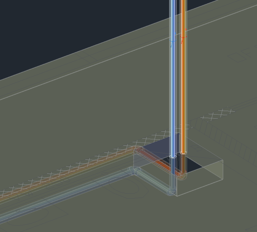
Goal: in the sample project draw a cold water riser of Piping 3D in the shaft from UG1 up to OG1, divide it across the three levels and then move it on EG.
By default the sample project divides at TOS: the dividing elevation between UG1 and EG is at 0 mm, between EG and OG1 at 3000 mm.
- On the project palette open the plumbing drawing of UG1, palette Piping 3D, page Risers/connectors.
- Insert risers/connectors: in the dialog box direction up, target up to level OG1, reference level FF, distance 1000 – below it reads "Target elevation 4.1 m" (FF of OG1 = 3100). Click in the shaft. The riser reaches from the start elevation −550 to 4100.
- Right afterwards the prompt Riser across levels appears: "The riser … reaches into OG1. Divide it across the levels now (Plumbing: UG1, EG, OG1)?" – "Divide levels at" is set to TOS. Divide now.
- The command line reports: "Divided: 1 riser(s), 2 piece(s) written into 2 drawing(s), 1 piece(s) stay in this drawing."
- Save and close the drawing of UG1, open the plumbing drawing of EG. Risers/connectors page › Move, select the riser and move it 200 mm toward the wall.
- Prompt Riser across levels moved with UG1 (below) and OG1 (above): Follow everywhere. UG1 and OG1 follow and are saved.
Settings: dividing plane, switch, prompt
Goal: set at which reference level the project is divided, whether the level function applies in the project and whether LuaCAD asks while you draw.
- Gear menu › Levels › Divide across levels settings … (or project palette › shortcut menu › Divide across levels settings …).
- Choose the three settings in the dialog box.
- OK writes the dividing plane and the switch into the project file, the setting for drawing into your personal settings.
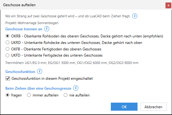
Divide levels at
One of the four reference levels that every project has (Elevations and reference levels):
| Choice | Dividing elevation | The slab belongs … |
|---|---|---|
| TOS – recommended, default | TOS of the upper level | to the lower level |
| BOS | BOS of the lower level | to the upper level |
| FF | FF of the upper level | to the lower level, including the floor build-up |
| FC | FC of the lower level | to the upper level |
Below the choice are the dividing elevations of each level boundary. If the reference level is missing on a level, TOS of the upper level applies there.
The dividing plane applies to the whole project and to everything divided from now on. Existing break points stay where they are – even if you change the dividing plane or a floor-to-floor height later. Check risers shows such places as a note.
If no dividing plane is set yet, LuaCAD asks with the small window "Divide levels at" (only the four reference levels) the first time you divide in the project. Canceling there = nothing is divided. The prompt when drawing and the tool "Divide objects across levels" show the same choice as a list; it is only remembered there when you divide.
Level function on/off
The check box Level function switched on in this project is stored in the project file and applies to everyone who works in the project. Switched off, LuaCAD works in the project as without the level function: no prompt when drawing, no dividing, existing level joints are ignored (rise/drop symbol, annotation and isometric then show "ends" instead of "continues on …"). On by default.
When drawing across a level boundary
ask (default), always divide or never divide – your own setting, for all projects and all three plug-ins. "Always divide" divides without asking; "never" keeps every riser you draw whole. You reset the check box "don't ask again" of the prompt here or in the LuaCAD settings (list of remembered answers).
Dividing while drawing
Goal: distribute a riser across the levels right when you draw it.
At the end of these commands LuaCAD checks whether a newly drawn riser crosses a dividing elevation by at least 10 mm:
| Plug-in | Commands |
|---|---|
| Piping 3D | Insert risers/connectors (target "up to level" or a fixed riser height), Insert pipe with a change of elevation, multiple pipes |
| Drainage 3D | Stack down or stack up with Stack across levels › To, stack of the in-wall carrier with To |
| Ventilation 3D | Duct run, round duct run and flexible duct with a vertical piece across the boundary |
- Draw as usual. If the riser reaches across a dividing elevation, the prompt "Riser across levels" appears after the command.
- Check "Divide levels at" (suggested is the reference level of the project, otherwise TOS).
- Divide now – each piece up to the level you drew to goes into its drawing. Or Not now: the riser stays whole in this drawing. If several new risers have different targets, the question names all of them, and each one is divided up to its own target (one step per target).
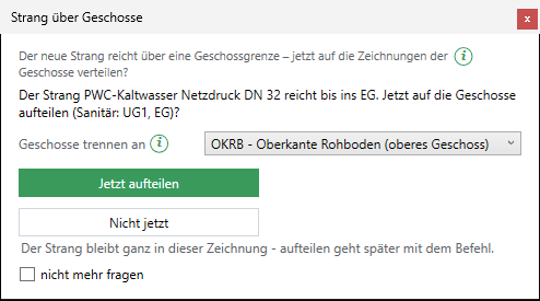
Dividing is a step of its own: the first U takes back only the dividing in this drawing, the second one the riser. With "don't ask again" LuaCAD remembers the answer as "always divide" or "never divide". A run that stays within the level never asks.
Dividing afterwards
Goal: distribute a riser that is already drawn across the drawings of the levels.
- Divide across levels … on the palette of the plug-in (table above) or gear menu › Levels. From the project palette LuaCAD first asks which plug-in should divide, if several are loaded.
- Select the risers: click them or drag a selection window, several times if needed; Enter = finish, Esc = cancel.
- If no dividing plane is set in the project yet, "Divide levels at" comes first.
- In the "Divide across levels" dialog box choose how far: Up to and Down to. All levels in between always go along.
- Divide.
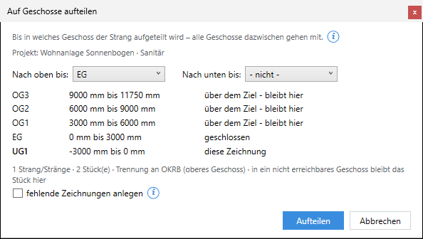
What happens to the drawings of the levels:
- closed: the piece is written into it and the drawing is saved;
- open in GstarCAD: changed but not saved (save it there yourself; U there takes the piece back);
- being edited by someone else, read-only or no drawing of this discipline: the piece stays in your drawing, the command line says why; if writing into a drawing went wrong (for example a layer locked there), the window Not divided everywhere also names the level with the reason. With the check box create missing drawings LuaCAD first creates a missing drawing from the template and then divides;
- a piece above or below the target stays in your drawing.
What is cut
- The riser is cut at every dividing elevation it crosses by at least 10 mm.
- A fitting is never cut. If it lies on the dividing elevation, the break point moves to its end – into the level the slab belongs to by the dividing plane (with TOS: down). Fittings close together (for example a coupling and a reducer) count as one part.
- Property fields go with their piece into the other drawing.
- A copy made with COPY carries no marker – it is a new riser of its own.
Piping 3D
A riser is the vertical routing lines of one axis with the same system. Parts placed by hand in the riser (valve, coupling by hand, custom part) are never cut and go with the piece in which their middle lies; if a break point is at the connector of such a part, the end of the routing line next to it carries the marker. If 3D is already generated, each piece is placed again and numbered in its drawing. If a pipe in the target drawing ends in the middle of the piece, a tee is placed there. More: Piping 3D › Divide across levels.
Drainage 3D
The riser is the stack symbol. It carries "up to level" (Connectors page › Stack across levels › To, default "– this level only –") and, after dividing, the markers. Divided means: every level up to the target gets the matching stack in its drawing – in between a stack passing through (with a wye), at the end a stack up or a stack down. If there is one already, it only gets the markers.
- With Divide across levels … you can also divide a stack without "To": the dialog box then suggests the lowest level (stack down) or the highest level (stack up).
- A stack is only divided if all levels up to the target can be reached; otherwise not at all, with a sentence on the command line.
- A level the stack only passes through (pass-through level, without a plumbing line) gets a stack pipe from dividing elevation to dividing elevation when 3D is generated.
- The load from above counts across all levels; "Fixed size" on the stack down keeps the chosen diameter.
- Parts placed by hand (pipe, fitting, "Connect") are not divided – "Divide objects across levels" only shows them.
- The stack of the in-wall carrier (In-wall carrier routing page › To, downward only) is distributed with the same name and inflow from above; the pieces meet exactly at the level boundary (Joint at the level boundary).
More: Stack across levels, In-wall carrier across levels.
Ventilation 3D
Ventilation has no lines – the riser is the 3D geometry: vertical straight ducts or round ducts of one axis with the fittings on them; it ends at an elbow (the elbow belongs to it).
- Surface-mounted parts (grille, tap, valve) go with their piece; they are never cut, the opening is cut again in the target.
- A duct that hangs on the riser only and lies entirely on another level goes along.
- If the target already has a vertical duct of the same system, it only gets the markers.
- On the other level a new duct run starts at the end of the vertical duct when the xref of that level is shown; the first part then gets the matching marker.
More: Ventilation 3D › Divide across levels.
Divide objects across levels
Goal: check the whole drawing for what reaches across a dividing plane and divide everything at once.
- Divide objects across levels … (palette of one of the three plug-ins or gear menu › Levels). First a help with a picture explains the list.
- Choose Divide levels at at the top – the list recalculates right away.
- One row with a check box per riser: "riser – elevation range → levels". All three plug-ins are always checked, no matter from which one you start. Show shows the riser in the drawing.
- Set or clear check boxes, Divide selected.
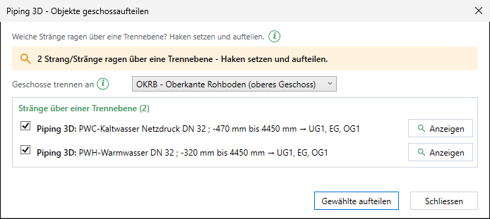
Each riser is divided up to the level in which it ends – one step per plug-in and target (U takes it back). The chosen dividing plane is remembered in the project. Rows without a check box (parts placed by hand in Drainage 3D) are for information only.
Following after moving
Goal: move a divided riser – the pieces on the other levels follow.
- Move the riser: on the palette (Move, in Piping 3D also Change elevation, Change properties, Edit risers/connectors) or with MOVE or a grip of GstarCAD.
- If something on another level is attached, the prompt "Riser across levels moved" appears with the list of levels (below/above, number of parts, open/closed).
- Choose:
| Button | What happens |
|---|---|
| Follow everywhere (preselected) | All connected levels above and below follow – position in plan, elevation at the joint. Pipes on the riser follow by the rules of the plug-in. |
| Follow only below | Only the levels below follow; the link upward is released afterwards. Grayed out if nothing is attached below. |
| Follow only above | Only the levels above; the link downward is released. Grayed out if nothing is attached above. |
| Do not follow | No other level changes; both links are released. |
| Esc or closing the window | Cancel: your own move is taken back, nothing is released. |
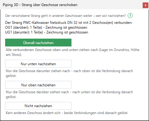
The riser is traced from joint to joint: if the piece on OG1 again has a piece on OG2 above it, OG2 follows too. If the part in a target drawing is on a locked layer, nothing is changed there; the command line names the layer.
A riser that was only drawn and never divided (Piping 3D, Drainage 3D) but has pipes of other levels ending on it asks more simply: "Follow on the other levels" with "Follow" | "Do not follow". There, open drawings are changed too (not saved). Ventilation 3D only follows divided risers.
The drawing must be closed
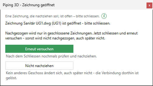
Following only happens in drawings that are closed and writable – so LuaCAD never changes a drawing someone is working on. If a target drawing of the chosen side is open, being edited by someone else or read-only, "Drawing is open" appears immediately:
- "Drawing Plumbing OG1.dwg (OG1) is open – please close it." (or "… is being edited by …", "… is read-only")
- Try again: close the drawing, then this button – LuaCAD checks again and follows.
- Do not follow: no other level changes, not later either; the link is released.
- Esc: cancel, your move is taken back.
Check risers
Goal: find where divided risers no longer match between the levels. It only checks, nothing is changed.
- Gear menu › Levels › Check risers … or project palette › shortcut menu.
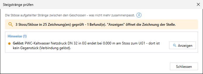
- LuaCAD reads all drawings of the project (open ones in memory, closed ones from disk) and compares every break point with its counterpart on the neighboring level of the same discipline.
- If everything is connected, the command line says so. Otherwise the issues list appears; Show opens or activates the drawing of the place.
| Issue | Meaning |
|---|---|
| Released (note) | There is no counterpart at the joint on the neighboring level (more than 50 mm away or deleted). |
| Offset (note) | The counterpart lies up to 50 mm next to it. |
| Elevation gap (error) | Elevation is missing or overlaps between the pieces (more than 1 mm). |
| Jump (error) | System or nominal size changes at the break point without a fitting. |
| Dividing elevation (note) | The break point is no longer at the dividing elevation of the project (floor-to-floor height or dividing plane changed) – it stays where it is. |
| No drawing (note) | The discipline has no drawing on the neighboring level. |
| Taken back (note) | Dividing or following was undone with U in one drawing and is still present in the other (only in this session). |
Undo across levels
U only works in the drawing where you use it. If you take back a dividing or following with U, the command line says where it is still present: "Undo only applies in this drawing: the dividing in EG, OG1 is NOT taken back there …". An open target drawing has an undo step of its own for the change – U there takes the piece back; a closed one is saved. "Check risers" lists such places as "Taken back".
Output: rise/drop symbol, annotation, isometric, IFC
At a break point the outputs show on which level the riser continues – as long as the level function is switched on.
| Output | What it shows |
|---|---|
| Rise/drop symbol (Piping 3D) | The direction across the joints: on the middle level "through", at the top "down", at the bottom "up". If a link is released, it shows the direction without the joint again. Drainage 3D: the type of the stack. Ventilation 3D has no rise/drop symbol. |
| Annotation | The fields Continues upwards and Continues downwards and the default template Riser across levels – for each plug-in in the folder of the risers or stacks (Default templates). Without a marker the two lines are left out. |
| Isometric, PCF (Piping 3D) | At the joint "continues on OG1" instead of "open end" if the counterpart on the neighboring level still exists (Isometric); the PCF writes the continuation there (PCF). |
| IFC | The project IFC connects the pieces at the break points by their position; the report says how many pieces on different levels were joined (IFC export). |
| Clashes | Pieces of the same plug-in and system that touch at a joint count as one object – no clash at the break point (Checking for clashes). |