
Example 3 – A horizontal branch
What it is about
In the basement of the sample plan three stacks come from the shafts of the bathrooms above. They are picked up below the basement ceiling, collected in a horizontal branch in the corridor and led down into the sewer at the outside wall.
The steps
- Insert a stack up per shaft – this is where the water arrives from above.
- Insert the sewer outlet – a stack down at the outside wall.
- Draw the pipes – horizontal branch in the corridor and the branch lines from the shafts, with slope in %.
- Set up the sizing – standard and building drain.
- Generate 3D and read the result.
- Fix and annotate elevations – spot elevation and invert.
1. A stack up per shaft
This is where the water from the levels above enters the horizontal branch.
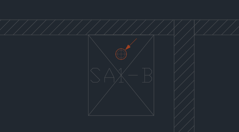
- General routing page: click the Stack up tile.
- Click into every shaft 1 – exactly below the stack of the level above.
- In the dialog box: the same short name as above (FL1, FL2, FL3), main fitting double 45° bend, top "below BOS" == 0.
More details
- If the drawing above is loaded as an xref, snap to its riser.
- Continuation above "pipe"; with top "below BOS" == 0 the stack ends at the bottom of the basement ceiling.
- Under Load from above: calculation "floor-level branch", sum DU and number of fixtures above. If the drawing above has a stack with 3D at the same place, "Generate 3D" takes the load from there.
2. Insert the sewer outlet
This is where the water leaves the building – the slope is built up from here.
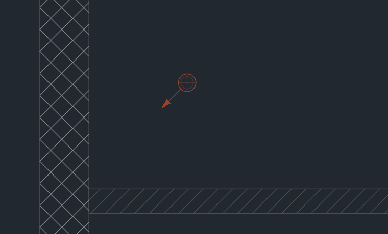
- Click the Stack down tile and click at the outside wall 1 where the pipe goes into the sewer.
- In the dialog box: short name "KA", main fitting double 45° bend, continuation below "pipe" with extension 1800.
- Fixed invert: "below BOS" == 700.
More details
The double bend turns the pipe down; the extension says how far it goes down. With the invert the horizontal branch hangs there 700 mm below the basement ceiling; from here it rises with the slope toward the shafts.
3. Draw the pipes
The horizontal branch in the corridor takes the branch lines from all shafts.
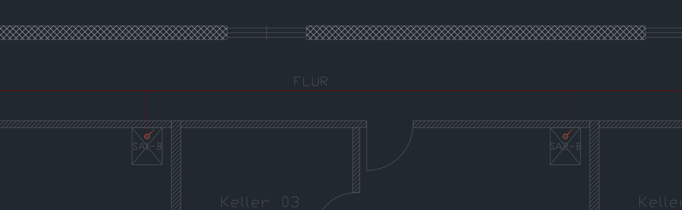
- Set the slope on the palette to 1 %.
- Insert line: start at the sewer outlet and draw the horizontal branch through the corridor to the last shaft 1; Enter.
- From every shaft draw a short line onto the horizontal branch 2.
More details
- The slope is always in %. Where a line meets the horizontal branch, "Generate 3D" places a wye.
- The drain type of the lines in the corridor is "horizontal branch / building drain" – check it with Properties (Plumbing line dialog box).
| Key | Effect |
|---|---|
| A | slope, elevation, wall offset and fixed length while drawing (dialog box while drawing) |
| Space | snap to angle / free |
4. Set up the sizing
The standard decides by which tables the horizontal branch and building drain are sized.
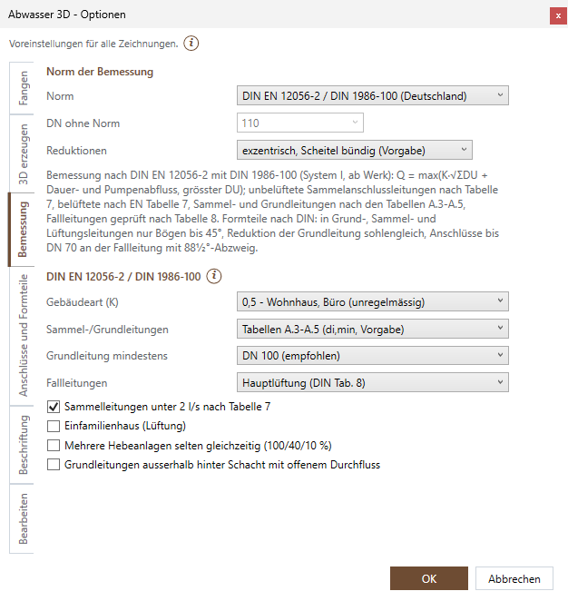
- Gear menu › Settings › Options, Sizing tab: check the standard 1.
- Under DIN choose the building type 5.
More details
- By default DIN EN 12056-2 / DIN 1986-100 applies, in Switzerland SN 592 000.
- The building type sets the frequency factor K; below it is the calculation of horizontal branches and building drains.
- Whether the pipe lies inside or outside the building you set in the dialog box of the sewer outlet under Building drain – each position has its table in the standard.
- What the standard makes of the values: Standard and diameter.
5. Generate 3D
The lines become the horizontal branch, wyes and double bends – sized with the load of all three stacks.
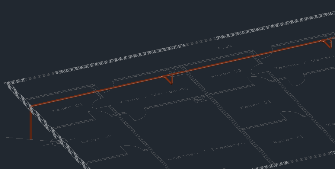
- Generate 3D and click the sewer outlet 1.
- Read the diameter, ΣDU, Qww and slope per section in the result.
More details
An error also appears as a marker in the drawing – for example when an elevation is not enough.
6. Fix and annotate elevations
A spot elevation forces the pipe to a fixed elevation at one place, for example at a wall penetration.
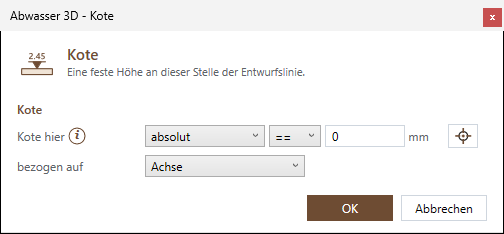
- Connectors/Offset page: place a spot elevation on the line – "from TOS", == −350 1, relative to invert 2.
- Generate 3D – the pipe passes through this elevation.
- Output page, Spot elevation tile, edge "invert", click the place.
More details
The invert here is the inside bottom on which the water flows. The slope stays when the pipe passes through the spot elevation. Annotating: see Annotating spot elevation and elevation. What invert, centerline and top mean exactly: Elevations.
What next?
Look up everything else – from Good to know through General routing to Output.