
Example 1 – A bathroom
From an empty floor plan to finished cold and hot water pipes in 3D: the bathroom of an apartment on the first upper floor of the sample project, the plumbing drawing of level OG1. The risers stand in the shaft at the top right, the pipes run in the in-wall carrier to the lavatory and the toilet. Each step has one sentence, one picture and the clicks – the light blue numbers in the text are the numbers in the picture above. Variants and details are collapsed under "More".
1. Open the palette and choose the values
What is set at the top of the Pipe page applies to every pipe you insert afterwards.
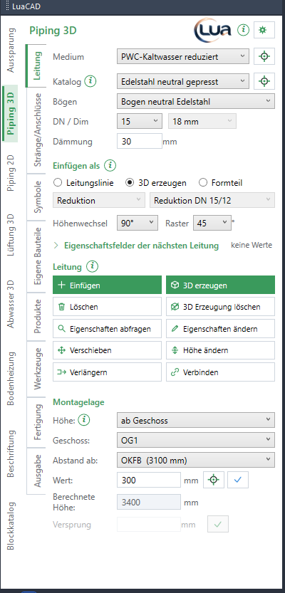
Ribbon › LuaCAD tab › Piping 3D – the palette opens on the Pipe page.
- 1 System "PWC cold water, reduced pressure" – it sets the color and the layer.
- 2 Catalog "stainless steel, generic, press-fit" and 3 DN 15.
- 4 Insert as "Generate 3D" (selected by default): pipes, elbows and tees are created while you draw.
- 5 You need Insert in step 4.
- 6 System elevation "from level", OG1, reference FF, 7 value 300 and Enter: the pipes lie 30 cm above the finished floor in the in-wall carrier.
More details
- Palette values apply only to parts you insert from now on – change what is already drawn with Change properties.
- With "Routing Line" you draw only the axes and generate the 3D later; the difference is explained under Basic concepts.
- The system elevation can also be absolute, a system elevation of the list or "free" (the elevation comes from the clicked point) – see Elevation and system elevation.
2. Insert the risers in the shaft
Cold and hot water reach the level through two risers. You insert both in one step from a riser template.
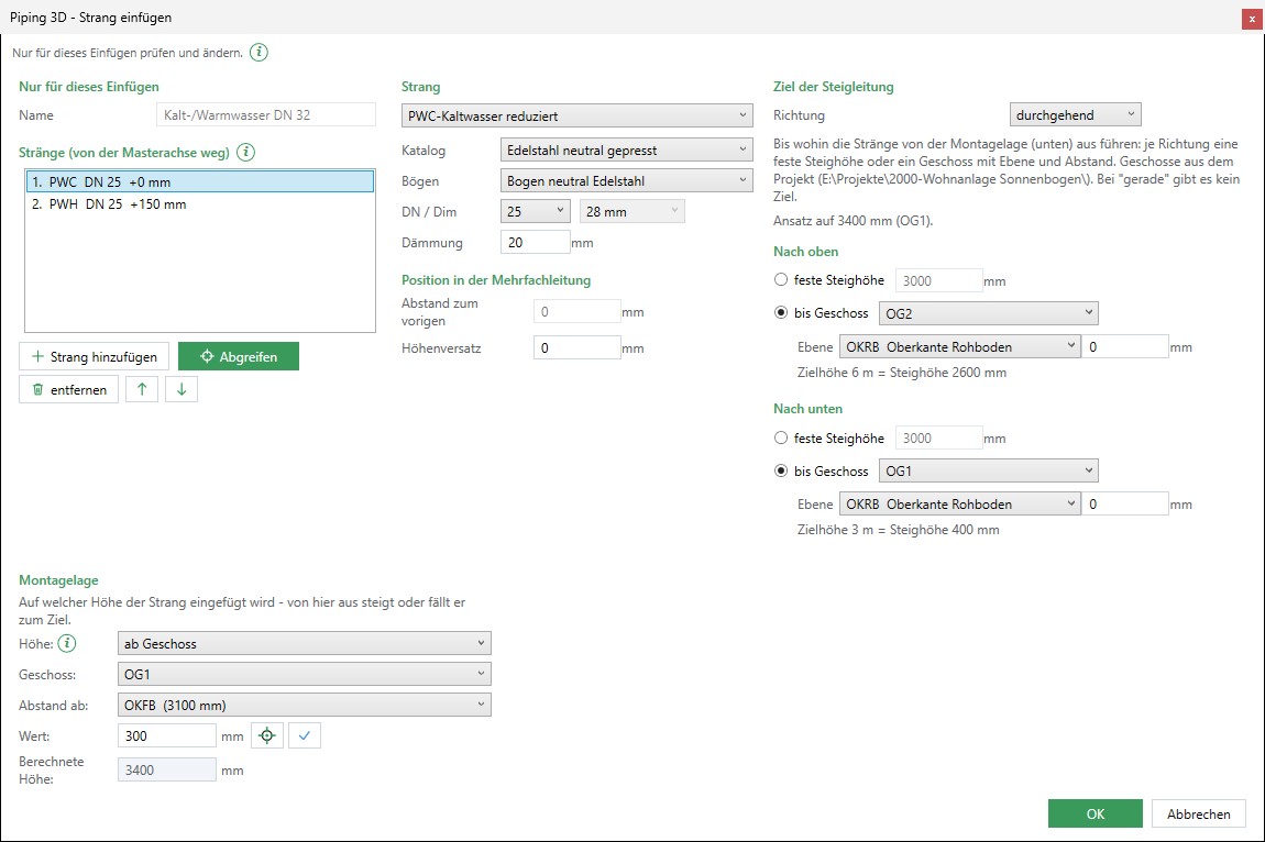
Risers/connectors page: choose the riser template for cold and hot water in the list, click Insert riser/connectors. In the dialog box:
- 1 The template brings two risers, PWC and PWH, 150 mm apart.
- 2 Click the PWC riser and choose the system "PWC cold water, reduced pressure", the generic stainless steel catalog and DN 25; do the same for catalog and DN of the PWH riser.
- 3 Direction "through" – the riser runs through the whole level.
- 4 Upwards to level OG2, reference TOS; 5 downwards to level OG1, reference TOS.
- 6 The system elevation FF + 300 from the palette: the pipes branch off at this elevation.
- 7 OK – the two risers hang on the cursor. Click into the shaft. The dialog box then opens for the next risers; Cancel ends.
More details
- What you change here applies only to this insertion; change the template itself under Managing riser and connector templates.
- On the cursor the Space key switches the riser you hold, R rotates the row.
- In the floor plan every riser is shown as a riser symbol: a circle with line and arrow on the diagonal as in DIN 1986-100 – with "through" the line goes through the circle.
- If the level function is switched on in the project and a riser crosses a level boundary, LuaCAD asks whether to divide it across the levels – see Divide across levels.
3. Place the connectors of lavatory and toilet
The pipe connectors mark where the pipes end: angle stops at the lavatory, the flush tank of the toilet.
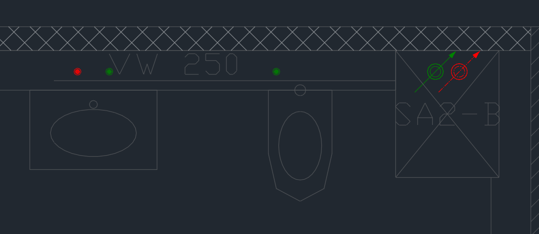
1 2 are the risers from step 2. Then on the Risers/connectors page:
- Choose the connector template for a lavatory in the lower part of the list, click Insert riser/connectors. In the dialog box set the system elevation to FF + 0 – the template brings the 550 mm of the angle stops itself – and click OK.
- The two connectors hang on the cursor. Rotate them with R so that the outlet points into the in-wall carrier and click in the middle of the lavatory into the carrier: 3 hot water on the left, 4 cold water on the right. Cancel in the next dialog box ends.
- Do the same with the template for a wall-hung toilet: 5 the connector of the flush tank at FF + 1000.
More details
- The elevation of a connector is always system elevation + offset of the template – with the system elevation FF + 300 from step 1 the angle stops would be at 850 mm. The command line names the elevation while inserting.
- Fixtures from the block library bring their connectors along – see Fixtures from the block library.
- More under Placing a pipe connector.
4. Draw the pipes
Each pipe starts at the connector of a fixture and ends on the riser or on a pipe that is already there.
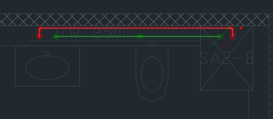
Pipe page, Insert:
- 1 Start at the connector of the toilet – the pipe goes down to the system elevation by itself and takes the DN 15 of the connector. 2 Click the cold water riser: the tee is created there. Enter.
- 3 Start at the cold water connector of the lavatory, 4 click the corner below the toilet – the elbow becomes a tee. Enter.
- For the hot water choose the system "PWH hot water" and the system elevation 400 at the top: it runs 100 mm higher, above the cold water pipe. 5 Start at the hot water connector, 6 the corner at the wall, 7 the corner in front of the shaft, 8 click the hot water riser. Enter.
Change the elevation while drawing
If a pipe has to go higher or lower in the middle of a run, for example below a beam, A on the cursor opens this dialog box:
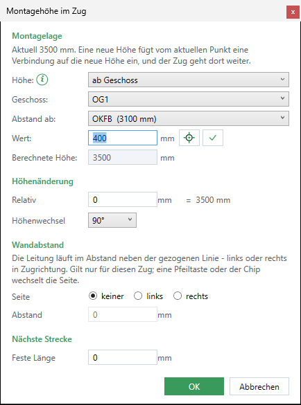
- 1 The elevation as on the palette: absolute, from level, system elevation or free.
- 2 Enter the new value, for example 400; 3 shows the elevation in the drawing (3500 mm).
- 4 Wall offset: the pipe runs at a distance next to the drawn line – left or right in the drawing direction, for this run only.
- 5 OK – a vertical piece to the new elevation is created at the current point and the run continues there.
More details
- The Space key switches between "snap to angle" (right angles, 45°) and free; the circle (in 3D the sphere) on the cursor shows how far pipe ends and connectors are caught.
- A pipe only connects to pipes of its own system – cold water never to hot water.
- All keys and options: Inserting a pipe, Elevation change while drawing.
5. The 3D
With "Generate 3D" as insert mode the 3D is done when the run ends: pipes, elbows and tees from the catalog, with 30 mm insulation.
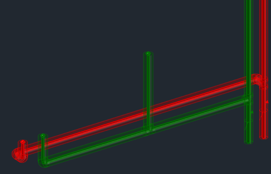
- 1 The risers get their 3D as soon as a pipe arrives at them.
- 2 4 Every branch gets a tee, reduced to DN 15 at the riser.
- 3 5 7 The vertical pipes to the connectors are created by themselves.
- 6 The hot water crosses the cold water 100 mm higher – without a fitting.
More details
- If you have drawn with "Routing Line", click Generate 3D (Pipe page) and click the pipes – see Generate 3D.
- LuaCAD numbers the parts of every network by itself (item numbers 3.1, 3.2 …); they appear in the parts list and can be annotated.
- Pipes are created in bar lengths with press couplings in between – see Pipe lengths and couplings.
6. Insert the shut-off valves
In front of the riser each pipe gets a ball valve – so the bathroom can be shut off.
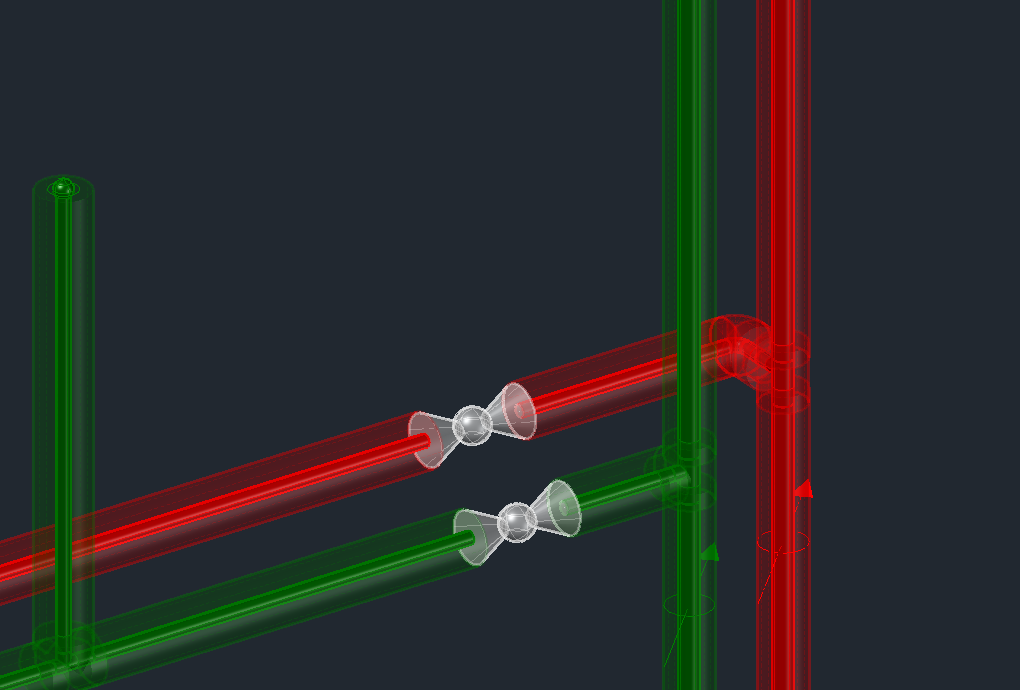
Symbols page: choose "ball valve", Insert, then:
- Click the cold water pipe in front of the shaft – the ball valve slides along the pipe –, click the position 2.
- Do the same in the hot water 1.
- 3 LuaCAD breaks the pipe, inserts the ball valve with the DN of the pipe and places the pipes next to it again.
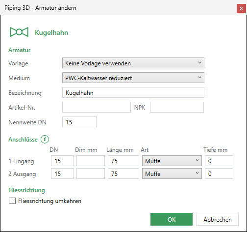
With Show the definition dialog box when inserting checked on the Symbols page – or later with Valve › Properties – this dialog box shows the values of the valve:
- 1 The system and 2 the description as it appears in lists.
- 3 The nominal size comes from the pipe.
- 4 DN, length and type per connector (here a press-fit socket).
- 5 For valves with a direction (check valves) this check box turns them around; 6 OK.
More details
More under Inserting a symbol, Inserting a part in-line and Changing a valve.
7. Query a part
Which part sits where, with which item number? Pipe page › Query properties and click the tee below the toilet:
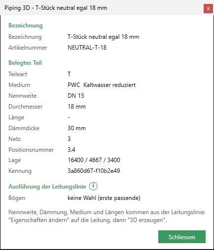
- 1 What the part is, with the article number from the catalog.
- 2 System and nominal size, below them diameter, insulation and network.
- 3 The item number 3.4 – the same as in the parts list.
- 4 The position in the drawing (x / y / elevation).
- 5 What the routing line specifies for elbows and tees. The part cannot be changed here: nominal size, insulation and system come from the pipe – use Change properties on the pipe, then the 3D is placed again.
More details
If you click a routing line instead of a part, the properties dialog box of the pipe opens. More under Querying properties.
8. Annotate and output the list
System and nominal size on every pipe – once per pipe is enough.
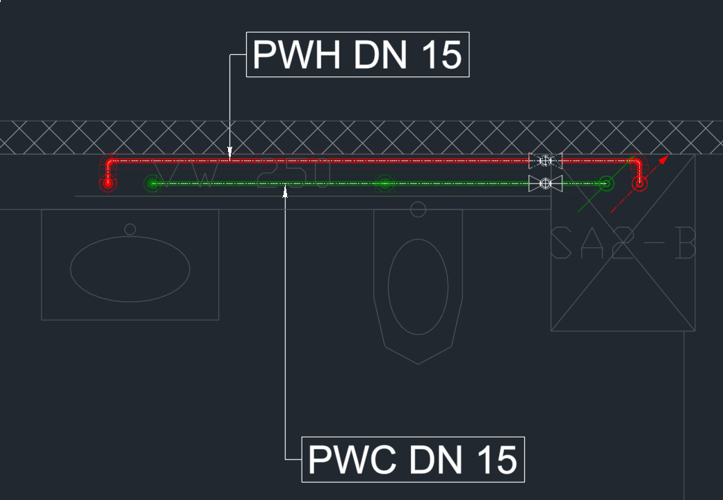
Output page › Annotate:
- 1 Choose the factory template for system and DN, click the cold water pipe and place the text in the room.
- 2 The same for the hot water – place the text beyond the wall so that the leaders do not cross.
- Bill of materials (Output page): the table hangs on the cursor, click next to the floor plan. It combines equal articles – the pipes with their length, elbows, tees and ball valves with their quantity.
More details
- The annotation sticks to the pipe: if you move the pipe, the text moves along. A changed template does not change annotations already placed.
- More under Annotating, Bill of materials and Parts list.
9. Change it afterwards
You edit like a CAD line – the 3D follows.
Edit with a grip
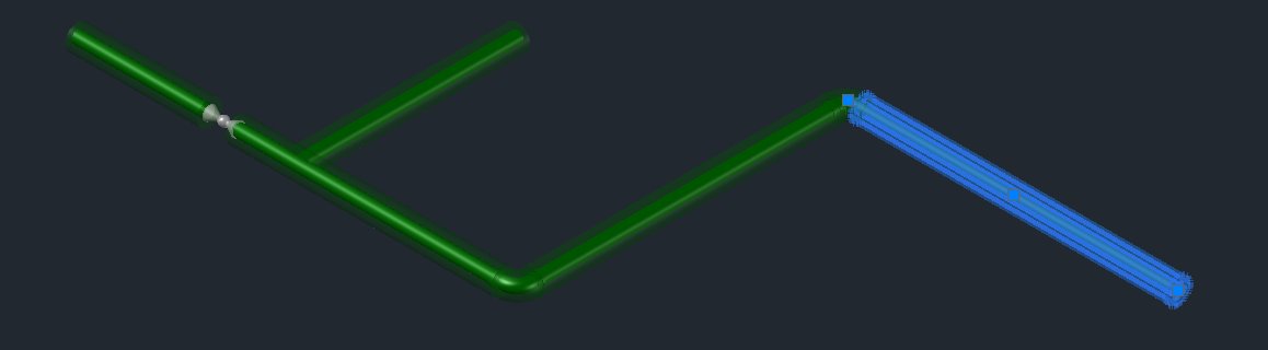
- Click the pipe (line or pipe) – 1 2 3 the grips appear.
- A free end moves only in the pipe direction, a corner freely, the middle grip moves the whole segment; neighboring pipes and the 3D follow at the end of the command. A valve 4 has a grip in its middle and slides along its pipe.
Move
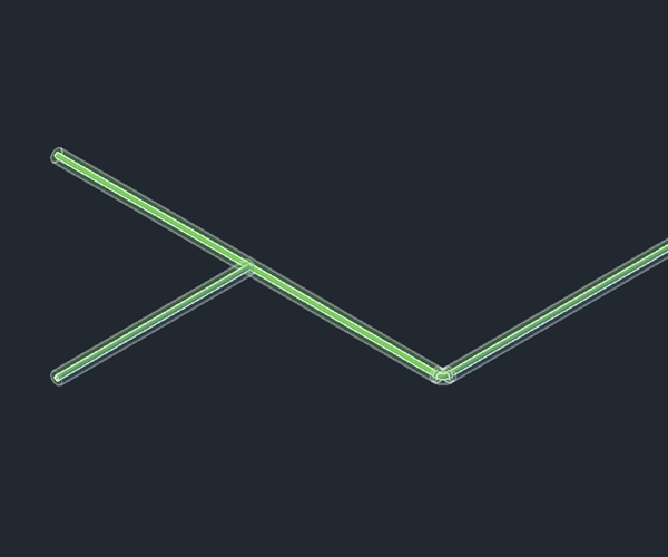
- Move (Pipe page) and click the pipe 1; Enter.
- Click the new position 2 – or press A and type a distance, for example 50. Connected pipes are shortened or extended, valves move along.
If the pipe has 3D, "Move" removes it while you select; then Generate 3D again. More under Moving pipes.
Change elevation
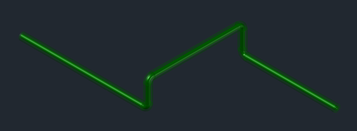
- Change elevation (Pipe page), select the pipe, Enter, choose the new system elevation in the dialog box – 1 the pipe lies at the new elevation.
- 2 3 Vertical neighbors grow along. Then Generate 3D. More under Changing the elevation.
Continue with example 2
The video shows example 1 once more as a whole; then continue with these pages.
- Example 2 – A distribution in the basement corridor: distribution pipes in the corridor, connecting with a tee, changing nominal size and elevation, inserting a ball valve, reading the issues.
- Example 3 – An isometric in process piping: welds, flow direction and the isometric with parts list.
Further ways
- Several pipes side by side (cold water, hot water, recirculation) in one run: Parallel pipes.
- A product with article number instead of a symbol: Adding and inserting a product.
- Esc cancels every function; another button on the palette cancels the running command and starts the new one. U undoes the last step.