
Example 2 – A piping plan step by step
The workflow
Goal: draw a plumbing plan on the floor plan of the sample project and then edit it - from the empty plan to the bill of materials.
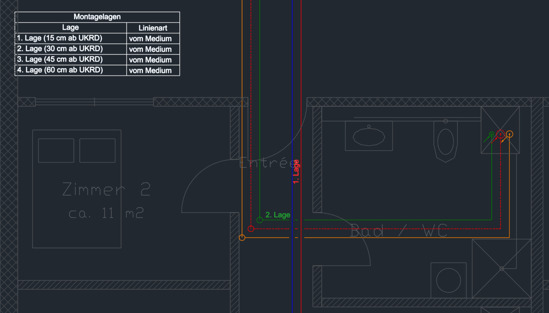
The main pipes run in the corridor along the wall, branch lines lead through the corridor wall to the shafts in the wet rooms. Proceed as follows:
- Draw the parallel pipes in the corridor
- Cross and change the system elevation
- Insert the risers in the shaft
- Connectors and pipe at the fixture
- Connect a manifold with PEX pipes
- Edit: system elevation, move, connect, break
- Put symbols into the pipe
- Elevation symbols and elevation table
- The bill of materials
1. Draw the parallel pipes in the corridor
First draw three pipes as parallel pipes along the corridor wall.
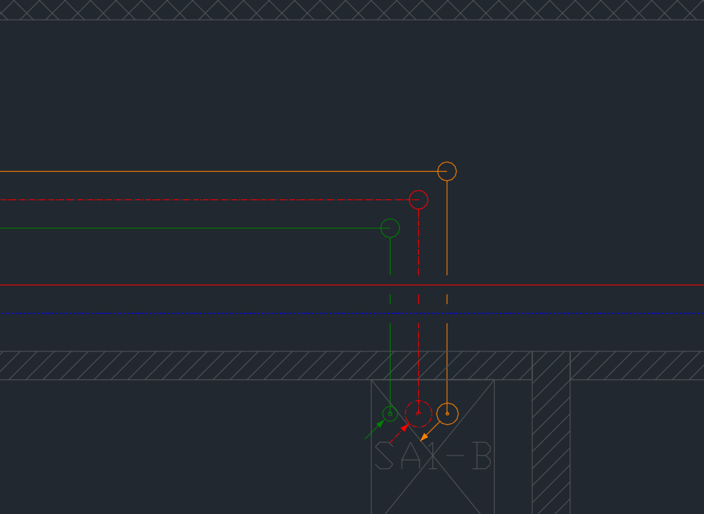
- Page Risers/connectors: choose a riser template with cold water, hot water and recirculation (three pipes at the spacing of the template) and under Parallel pipes the system elevation "2. Lage".
- Click Insert parallel pipes, click at the start of the corridor, enter the distance to the corridor wall with A.
- Draw along the corridor, click at the corner, draw through the corridor wall into the shaft, Enter.
Keys at the cursor
| Key | Effect |
|---|---|
| A | wall offset, system elevation, fixed length |
| S | the pipes to the other side of the drawing line |
| Enter | end the run |
2. Cross and change the system elevation
Where pipes cross or change the system elevation, the plan shows a gap and a circle.
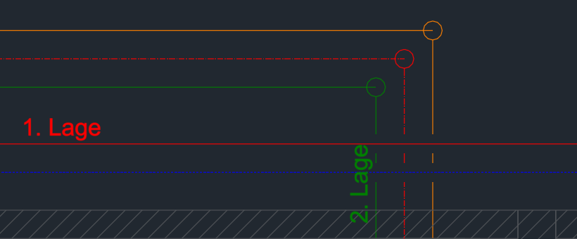
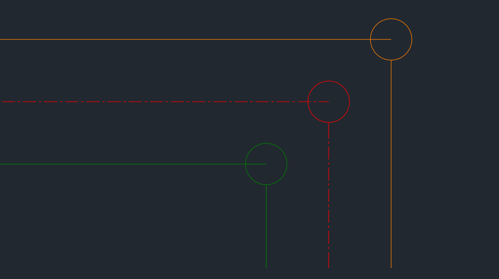
- Crossing: where two pipes of different system elevations cross, LuaCAD interrupts the lower one by a gap - automatically, also when you move one of them later.
- Elevation change: press A while drawing and choose another system elevation; a circle appears at the corner. The upper pipe runs to the center of the circle, the lower ends at its edge.
More: Crossings, Elevation change.
3. Insert the risers in the shaft
In the shaft you place the risers as rise/drop symbols.
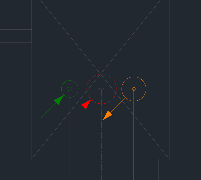
- Page Risers/connectors: choose the riser template, Insert risers/connectors.
- The risers hang at the cursor, the arrow is on the diagonal (up = top right). Space switches the riser you hold; click into the shaft.
- The branch line from step 1 ends at the riser: going down in the center, otherwise at the circle.
More: Insert riser.
4. Connectors and pipe at the fixture
At the fixture you place the connectors and run the pipe to the riser.
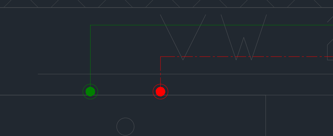
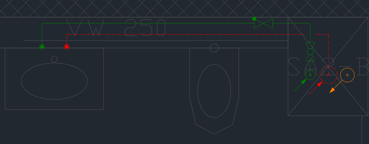
- Page Risers/connectors: under Connectors choose the lavatory template and place it at the lavatory - cold water left, hot water right.
- Page Pipe: Insert pipe, start at the connector (system and size come from the connector), draw over the corners to the riser.
- For a PEX pipe check flexible: every corner is rounded.
More: Connector, Pipe, flexible.
5. Connect a manifold with PEX pipes
A manifold in the in-wall carrier gets flexible PEX pipes to the fixtures.
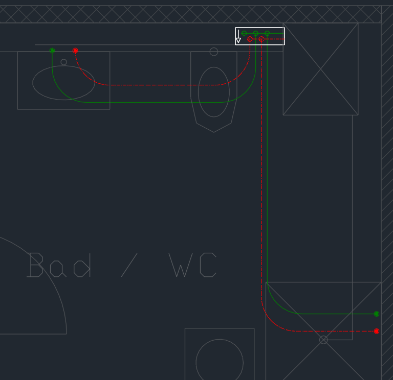
- Page Manifold: choose a template (systems, number of outlets, box), Insert manifold, align with R, place it in the in-wall carrier.
- Connect PEX: select the manifold and the connectors of the fixtures. LuaCAD shows complete solutions; the selected one has the fewest crossings.
- Enter accepts. Every used outlet is stored at its pipe.
6. Edit: system elevation, move, connect, break
Here you change the system elevation and the route of the drawn pipes.
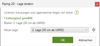
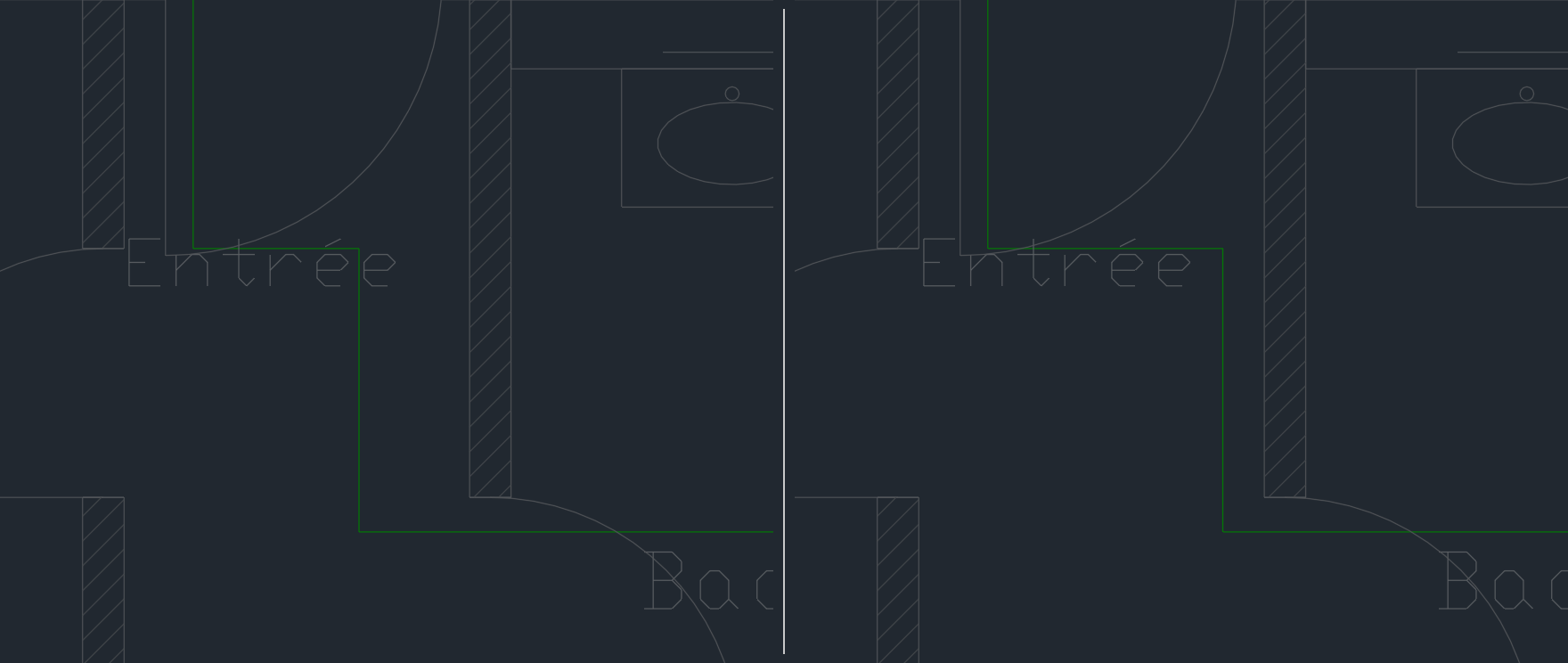
- Change system elevation (footer Tools): select pipes, choose the new system elevation in the dialog. LuaCAD recalculates crossings and elevation changes - a pipe that is now on top runs through.
- Move: select pipes and move them sideways; connected pipes become longer or shorter, circles and symbols move along. The same works with the grips of GstarCAD.
- Connect: click two pipe ends or an end and a pipe; LuaCAD suggests routes, if the second pipe continues a tee is made instead of trimming.
- Break and Join: break a pipe at a point or remove the break point again.
More: Change system elevation, Move, Connect, Break.
7. Put symbols into the pipe
You put valves into the pipe as symbols.
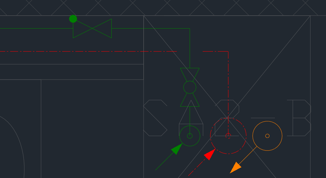
Page Symbols: click the symbol, Insert, click the pipe - it turns into the pipe, the pipe gets a gap. More: Symbol.
8. Elevation symbols and elevation table
Elevation symbols and the elevation table show the system elevation of each pipe.
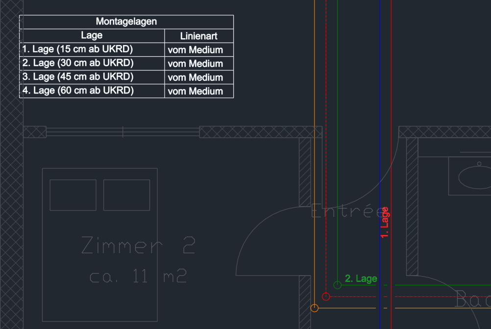
Page Elevations: Draw elevation symbols puts the short name of its system elevation at every pipe, the elevation table places the table of system elevations with their heights in the plan. More: Elevation symbols.
9. The bill of materials
Finally, output the bill of materials.
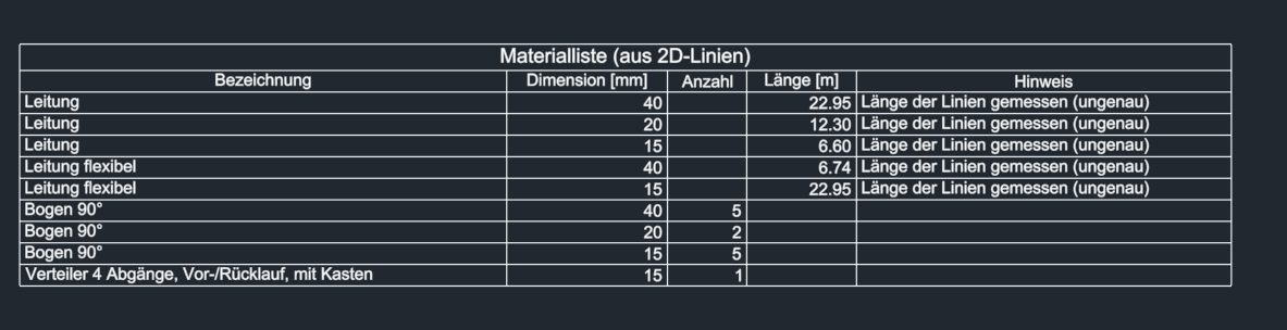
Footer or page Elevations > Bill of materials: the list counts pipes with length per size, elbows, tees and elevation changes from the geometry, manifolds and symbols with count. Example: "pipe 28, 12.4 m". More: Bill of materials.