
CAD basics
LuaCAD runs inside GstarCAD. The 3D plug-ins draw in the plan, but the result stands in space – so you need five moves of the CAD, no more. Here they are in short; everything else is explained by the GstarCAD help (F1).
| Move | How | Section |
|---|---|---|
| Orbit the view | hold Shift + middle mouse button and drag | Orbit the view |
| Top, Front, Isometric | click the ViewCube at the top right | Views |
| Two viewports | View tab › Viewports › Two | Two viewports |
| Zoom and pan | turn or press the mouse wheel | Zoom |
| Wireframe or shaded | View tab › Visual Styles | Visual styles |
Orbit the view
Goal: look at a pipe or duct from above at an angle without leaving the drawing.
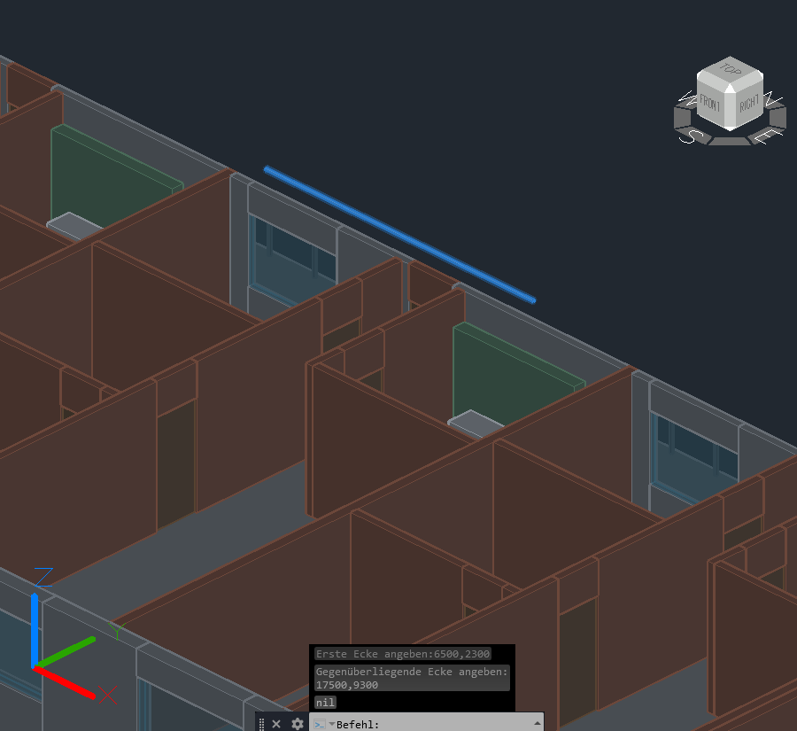
- Hold Shift, press the middle mouse button (the wheel) and drag – the view orbits around the drawing (1). Release, done.
- Back to the plan: click Top on the ViewCube (2).
Dragging a part at the cursor works the same way: LuaCAD never assigns Shift – the key belongs to the CAD.
Views: top, front, isometric
Goal: switch to a fixed view with one click.
- ViewCube at the top right of the drawing: a click on Top shows the plan, on Front or Left an elevation, on a corner of the cube an isometric view. The arrows next to the cube rotate by 90°, the small compass points north.
- The same in the ribbon: View tab › Views ribbon panel › Top, Bottom, Left, Right, Front, Back, SW Isometric and so on (command
_-VIEW, then for example_TOPor_SWISO).
| View | What it is for in the 3D plug-ins |
|---|---|
| Top | Drawing – routing lines, duct runs, design lines in the plan |
| Front, Left | Checking elevations – does the pipe pass above the door, below the ceiling? In an elevation view you also draw vertically (elevation change) |
| SW Isometric and the other isometric views | Checking and pictures – everything at a glance |
Two viewports
Goal: draw in the plan on the left and see the 3D on the right right away.
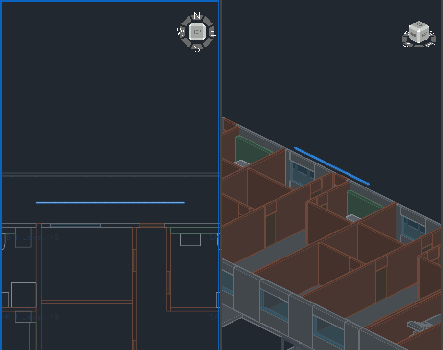
- View tab › Viewports ribbon panel › Two › vertical (command
_VPORTS). The drawing area is divided, both viewports show the plan. - Click into the right viewport – it becomes active (blue frame) – and choose an isometric corner on its ViewCube (1, 2).
- Draw in the left viewport and the right one follows immediately. A click into a viewport makes it active; the command line and the palette always apply to the active one – the left one in the picture (3).
- Back to one viewport: View tab › Viewports › Single (command
_-VPORTS, then_SI).
Zoom and pan
- Turn the mouse wheel: zoom around the cursor.
- Press the mouse wheel and drag: pan the view.
- Double-click the mouse wheel: show everything (Zoom Extents, command
_ZOOM›_E). - The same applies in an orbited view – zooming and panning do not change the viewing angle.
Visual styles
Goal: clear lines in the plan, solids with edges in the 3D view.
Video coming soon: CAD basics
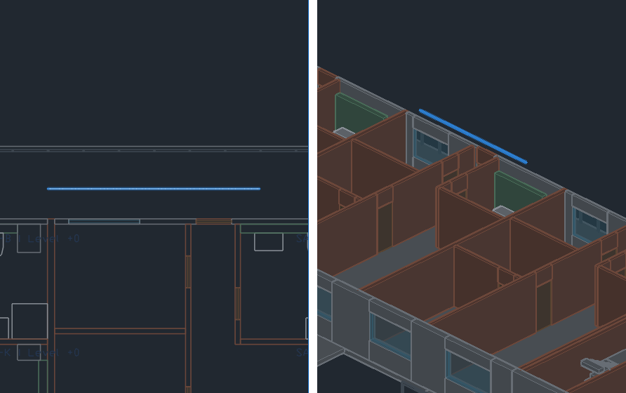
- 2D Wireframe for the top view: thin lines, everything visible – that is how you draw.
- Shaded with edges for isometric and elevation views: pipes, ducts and the IFC model as solids with edges.
- Switching: View tab › Visual Styles (command
_VSCURRENT). The style applies per viewport – wireframe on the left, shaded on the right is common.