
Example 1 – Floor heating for one room
From an empty floor plan to an annotated loop: room 2 of apartment A2 on the first floor of the sample project, in the heating drawing of that level. The room has about 11 m²; its door leads into the entrance hall of the apartment, where the manifold hangs on the wall opposite the room door. One sentence, one picture and the clicks per step – the light blue numbers in the text are the numbers in the picture above. Variants and details are collapsed under "More".
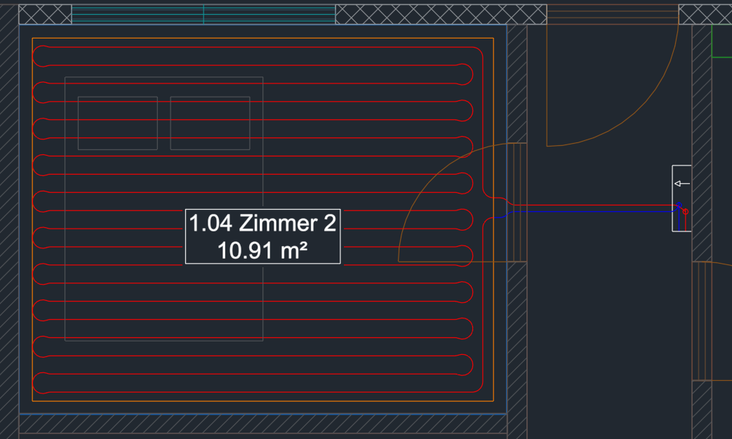
1. Open the palette and enter the values of the room
Ribbon › tab LuaCAD › Floor Heating. The palette opens at the edge of the drawing, the first time on the Rooms page; at the top are the values for the next room.
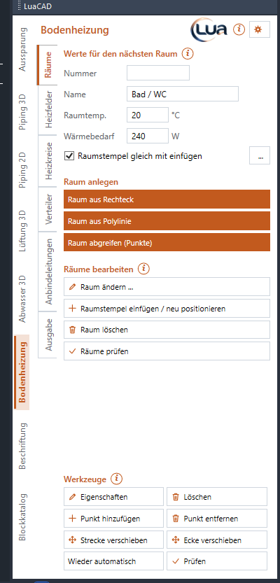
- 1 Number 1.04 – it applies only to the next room and is empty again afterwards.
- 2 Name Zimmer 2 (room 2).
- 3 Leave the room temp. at 20 °C – it is a value for the room tag and the list.
- 4 Insert room tag right away is on by default: the room gets its annotation right away.
- 5 The next step starts with Rectangular room.
More details
- Heated area, loop and leaders are derived: LuaCAD rebuilds them from the room and the values as soon as something changes – you change the room or the values, not the pipes.
- Palette values apply only to parts you insert from now on. What is already drawn you change with Change room, Change loop or the tools.
2. Insert the room
A room is a closed outline along the inside faces of the walls.
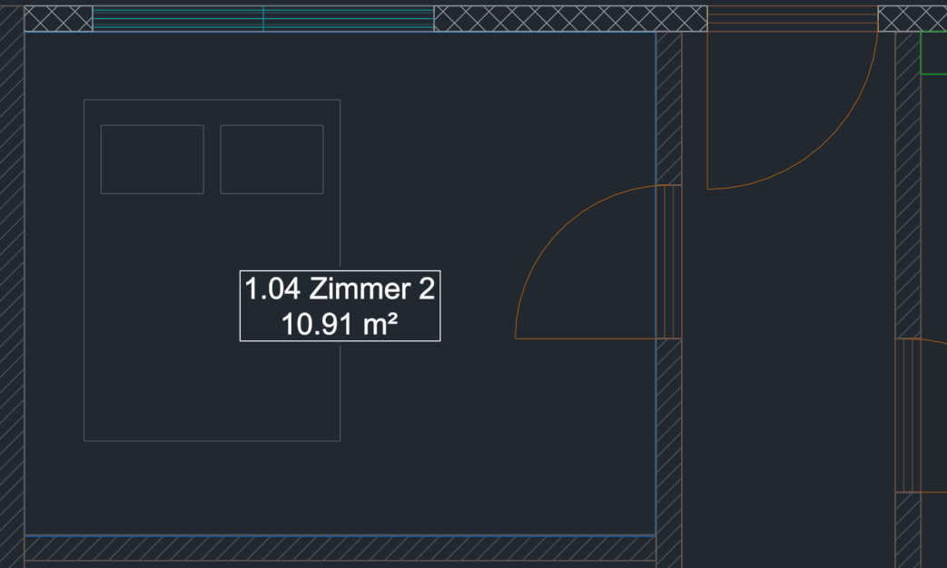
- 1 Click Rectangular room and click the first corner on the inside face of the walls – object snap helps.
- 2 Click the opposite corner. Enter finishes; the next room would follow right away.
- 3 The room appears with its room tag "1.04 Zimmer 2 – 10.91 m²"; the command line shows area and perimeter.
More details
Rooms with angled walls are inserted from a polyline or corner by corner – see Room from polyline and Pick room.
3. Generate the heated area
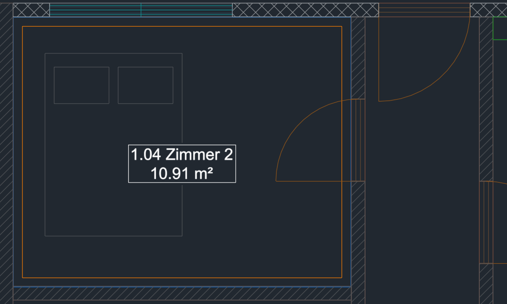
Open the Heated areas page; the edge distance is 100 mm by default.
- 1 Click Generate heated areas and click into the room: the heated area appears, the command line shows its area (9.62 m²).
- 2 The edge distance between wall and area stays free – that is where the edge insulation strip goes.
More details
Leave out a shower, a kitchen counter or a shaft with an exclusion area; divide a large room with Divide area.
4. Place the loop at the door
Supply and return are to leave the area at the door, which is in the middle of the wall. A counterflow pattern always connects at a corner of the area, a serpentine pattern also in the middle of a wall – so we choose the serpentine pattern here.
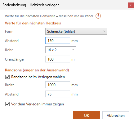
Place loop ... on the Loops page first opens this dialog box with the values of the palette.
- 1 Set Pattern to Serpentine (single); leave spacing 150 mm, pipe 16 x 2 and maximum loop length 100 m.
- 2 OK.
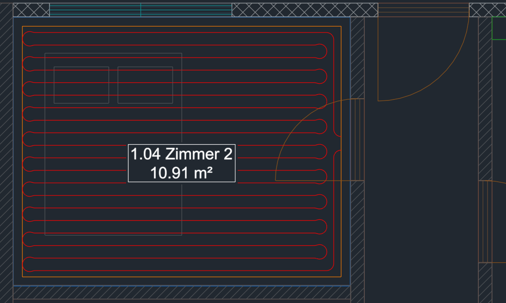
- 1 Move the cursor over the heated area – the loop is already visible – and click into the area.
- 2 Click the connector point at the edge of the area opposite the door. The loop is created; the command line shows its length in the area (71 m). Enter finishes.
More details
- Enter instead of a click chooses the connector point automatically: toward the manifold, or where a leader corridor enters the room – see Choose connector point.
- If the loop were longer than the maximum loop length, LuaCAD divides the area into several loops – see Maximum loop length.
5. Insert the manifold in the entrance hall
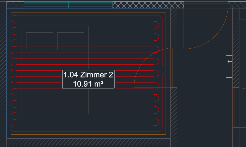
Open the Manifold page; by default the number of outlets matches the loops. Click Insert manifold … and OK in the manifold dialog box.
- 1 The manifold hangs at the cursor; click on the wall of the entrance hall opposite the room door.
- 2 Before that, rotate it with R until the arrow points to the door.
The loop gets its outlet right away – its number now reads 1.01 (manifold 1, outlet 1). Enter finishes.
6. Connect the loop
Open the Leaders page, click All/several loops at the bottom, then Enter = all loops of the manifold.
- 1 If there are several manifolds, click the manifold first; here it is unambiguous.
- 2 Supply and return run through the door at a center distance of 50 mm.
- 3 They end at the connector point of the loop; the command line shows the length (about 3 m).
If the door is not between manifold and connector point
The leaders do not know the walls – they know rooms, heated areas and leader corridors. If the manifold is farther away or the loop connects at a corner, first draw a leader corridor through the hallway and the door; the leaders then stay on the corridor and leave it only in the room of their loop. See Example 2 and Insert leader corridor.
7. Annotate the loop
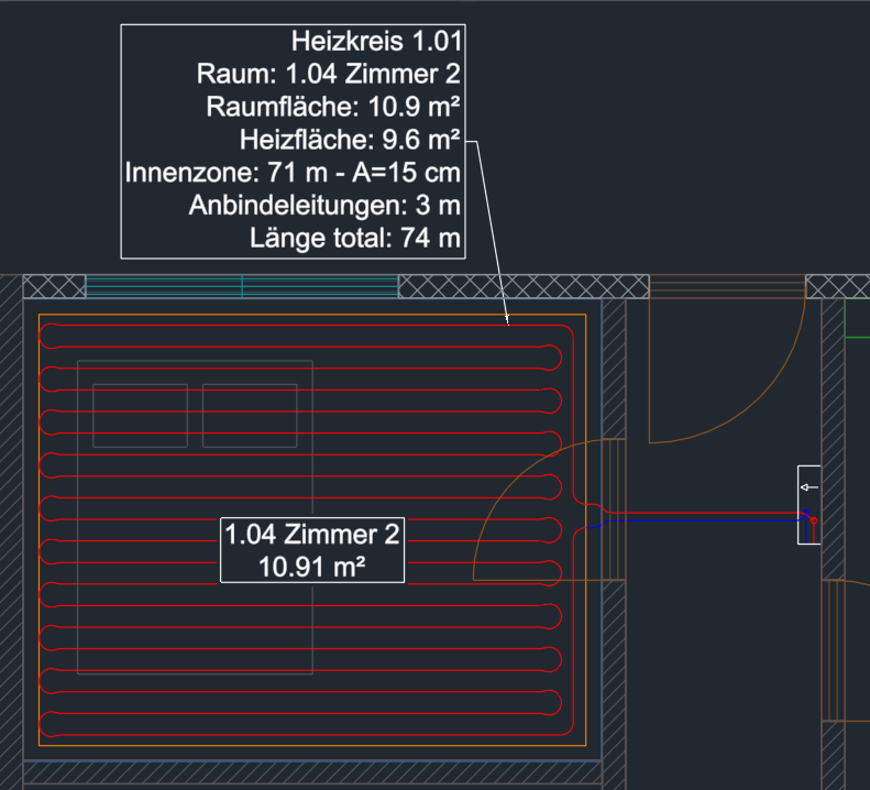
Output page › Annotate, template "Loop (Floor Heating)".
- 2 Click the loop near the place where the text should go – here at the top edge of the area.
- 1 Place the text above the room. It shows loop 1.01, room, room area 10.9 m², heated area 9.6 m², inner zone 71 m at A=15 cm, leaders 3 m and total length 74 m – and follows the loop when it changes.
- 3 The room tag has been there since step 2.
8. Create the bill of materials

Output page › Bill of materials and click a corner for the table – that is the order for this room. Whether the list comes as a table or as a file is set under List options.
9. Afterwards: change the room with a grip
- Click the outline of the room – the GstarCAD grips appear.
- Click a corner grip (1), drag it and click at the new position.
- Answer the prompt Room changed: Adapt rebuilds heated area and loop (2), leaders and room tag follow (3); Keep leaves area and loop as they are – they then count as "by hand". One U undoes everything in one step.
More in Editing rooms with GstarCAD.
10. Afterwards: change the loop
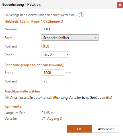
Click Change loop ... on the Loops page (or Properties under "Edit leaders") and click the loop. The dialog box shows 1 number, 2 pattern, 3 spacing, 4 pipe, 5 perimeter zone, 6 Connector point automatic and 7 the key figures. Set, for example, the spacing to 100 mm – OK: the loop is placed again, leaders and loop text follow.
More in Changing a loop.
What next?
The video shows example 1 once more as a whole; then continue with these pages.
- A whole apartment with a leader corridor through the doors: Example 2.
- Tighter spacing at the exterior wall: Choose perimeter zone.
- Loop schedule and more annotation: Output.
- Esc cancels any function; another button in the palette cancels the running command and starts the new one. One U undoes the last step.